Advertisement
Quick Links
Advertisement

Summary of Contents for AFFIX MADW-AGR Series
- Page 1 EN1004-1 Class 3 No: CE/21-22/044 Assembly Manual Double Width MADW-AGR Series...
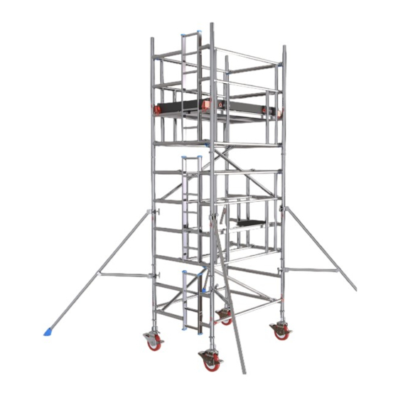
- Page 2 Aluminium Double Width Mobile Towers MADW 520 - AGR EN1004-1 3 7/11 XXXD This AFFIX Tower is a mobile access tower manufactured in our ISO 9001 This AFFIX Tower is a mobile access tower manufactured in our ISO 9001 accredited facility.
- Page 3 AGR frames form the midrail and guardrail above the platform level. This process repeats until the tower reaches the required height. Compliances: The Affix MADW Mobile Tower has been tested and certified to EN1004-1:2020 by TUV, India.
-
Page 4: Usage Advice
250 kgs evenly distributed. If the tower is to be used in an application outside the scope of EN1004, contact your supplier or the manufacturer, Affix Scaffolding WLL, for advice on loadings. - Page 5 USAGE ADVICE Air speed and resultant action to be taken Beufort Scale Description Air Speed Action to be taken Calm, smoke rises easily upwards 1 mph No action needed 12 mph Moderate breeze, raises dust No action needed, keep a watch Raises loose papers, leaves and small 17 mph Cease work...
- Page 6 SAFE WORKING LOADS AND WARNING HEIGHTS NEVER STAND ON AN UNGUARDED PLATFORM Safe working load on the working platform is 250kgs evenly distributed. The load on the tower should not exceed 750kgs. The maximum recommended tower height is 7M for outdoors and 11M for indoors.
-
Page 7: First Level
ASSEMBLY FIRST LEVEL Step 1 Insert the Castor Wheels with the jack pipe inside the bottom of the tubes of the 1st level 2 Rung Ladder Frame and 2 Rung Span Frame. DO NOT USE Hammer. DO NOT USE Hammer. Step 2 Step 2.1 Step 2.1... -
Page 8: Second Level
ASSEMBLY SECOND LEVEL Step 3 Step 3.1 Step 3.1 Insert both the 2nd level 4 Rung Span Frame and the 4 Rung Ladder Frame on the respective sides into the corresponding spigots. For clamping instructions refer to the Clamping Instructions section on Page 12. - Page 9 ASSEMBLY Step 5 Step 5.1 Step 5.1 Hook the top rung of the AGR frame to the top rung of the 2nd level frames and the bottom rung of the AGR frame should be hooked to the 1st rung of the 2nd level frames.
- Page 10 ASSEMBLY Step 7 Step 7.1 Step 7.1 Hook the Intermediate Trapdoor platform on the 2nd Rung of the 2nd level frames. Make sure the trapdoor is towards the ladder side. THIRD LEVEL Step 8 Step 8.1 Step 8.1 Insert both the 3rd level 4 Rung Span Frame and the 4 Rung Ladder Frame on the respective sides into the corresponding spigots.
- Page 11 ASSEMBLY Step 9 Step 9.1 Step 9.1 Hook the Diagonal Brace to the 3rd Rung of the 2nd level Span frame at one end and the other end should be hooked to the 1st Rung of the 3rd level Ladder frame. Step 9.2 Step 9.2 Hook the 2nd Diagonal Brace to the 3rd...
- Page 12 ASSEMBLY Step 11 Step 11.1 Step 11.1 Hook the Working Trapdoor platform on the 2nd Rung of the 3rd level frames. Make sure the trapdoor is towards the ladder side. Step 11.2 Step 11.2 Also hook the Fixed platform beside the Trapdoor platform on the same rungs Step 12 Step 12.1...
- Page 13 ASSEMBLY Side ToeBoard ToeBoard Fix the claw of the Toeboard TB on the Then insert the Side Toeboard and the End Rungs facing each other as shown in the Toeboard in the respective toeboard slots figure. as shown in the figure. Spring Clip Always ensure the Spring Clips are in the lock position after inserting the upper...
- Page 14 COMPONENTS FS20135 FL20135 CW150/200, JA500 Span Frame Ladder Frame Castor Wheel, Adjustable Jack FS10135 FL10135 BT200/250 Span Frame Ladder Frame ToeBoard Set...
- Page 15 COMPONENTS BD200/250, BH200/250 ST200/300/450/600 Diagonal Brace, Horizontal Brace Stabilizer AGR200/250 Advanced Guard Rail PF200/250 PT200/250 Trapdoor Platform Fixed Platform...
- Page 16 STABILIZERS Stabilizers are to be used, when specified, to guarantee the structural stability of the tower. Fig. 02 Fig. 02 Fig. 03 Fig. 03 Fig. 01 Fig. 01 Fig. 04 Fig. 04 Fig. 01 Fig. 01 Lightly tighten the upper clamp of the stabilizer on each corner vertical posts at a height where the foot is touching the ground.
- Page 17 STABILIZERS To move the tower to a new position, first prepare the tower. Check that the wind speed does not exceed 17 mph. Ensure the tower is empty (material and personnel). Check the overhead obstructions including electrical cables. Raise the stabilizer feet (only enough to clear obstructions, maximum 25mm). Taking care to ensure tower stability is maintained, release the castor brakes.
- Page 18 COMPONENTS TABLE MADW SERIES TABLE confirming to EN1004 ALUMINIUM DOUBLE WIDTH TOWER - AGR Method...
- Page 20 PO Box No. 201633 Doha, Qatar Mobile +974 4416 1483 +974 5529 9893 Mobile +974 3030 0685 EMail : info@affixscaffolding.com Website: www.affixscaffolding.com To Check Assembly Video SCAN ME https://qrco.de/bcPyx6 https://twitter.com/affixscaffoldin https://twitter.com/affixscaffoldin https://www.facebook.com/affixscaffoldin https://www.facebook.com/affixscaffoldin https://www.linkedin.com/company/affix-scaffolding-llc/ https://www.linkedin.com/company/affix-scaffolding-llc/...
Need help?
Do you have a question about the MADW-AGR Series and is the answer not in the manual?
Questions and answers