Table of Contents
Advertisement
Quick Links
Advertisement
Table of Contents

Summary of Contents for HANMEY IGN Series
- Page 1 1GN SERIES ROTARY CULTIVATOR OPERATOR’S MANUAL...
-
Page 2: Table Of Contents
CONTENTS C H A P T E R Ⅰ M a i n t e c h n i c a l s p e c i f i c a t i o n s … … … … … … … … … … … … … … … … … … … … … 2 C H A P T E R Ⅱ... - Page 3 2 . 8 T a i l i n g b a r … … … … … … … … … … … … … … … … … … … … … … … … … … … … … … … … … … … … 4 C H A P T E R M e t h o d s o p e r a t i n g...
-
Page 5: Chapter Ⅰmain Technical Specifications
Chapter ⅠMain technical specifications These series rotary tiller, are driven by the power-take-off of tractor. It is a kind of excellent equipment and secondary tillage. It can match with 18.4-44.1 kw (25-60HP) wheel-tractor, working on unplowed and plowed field. It has the characteristics of cold smaller on dry tillage, clay mashed and enough slurry on paddy field, surface soil smooth, good coverage with weed and stubble, working depth uniform, efficiency high. - Page 6 Joint manner Standard three-point linkage Overall dimensions 1450×800×700 1550×800×700 1700×800×700 2000×800×700 (L×W×H)(mm) Total quality (kg) Quality of gear oil Gearbox≈2.5 side transmission box≈4 (kg) Working in dry paddy fields and caked rice fields, rotating tillage and cutting off green manure at 100kg/ha, shallow tillage in saline-alkaline land below average, tillage in Application scope vegetable garden, land reclaiming, etc.
-
Page 7: Chapter Ⅱ Brief Introduction On The Structure And Their Adjustment
Chapter Ⅱ Brief introduction on the structure and their adjustment These catena rotary tillers are tillage equipment by means of the compound motion both of the rotation of the tractor going forward. It consists of universal coupling, headstock, gearbox, side chain box (gearbox) are transmission sets. Blade and blade shaft are working parts. Headstock, the cover and trailing bar are sets assistant. -
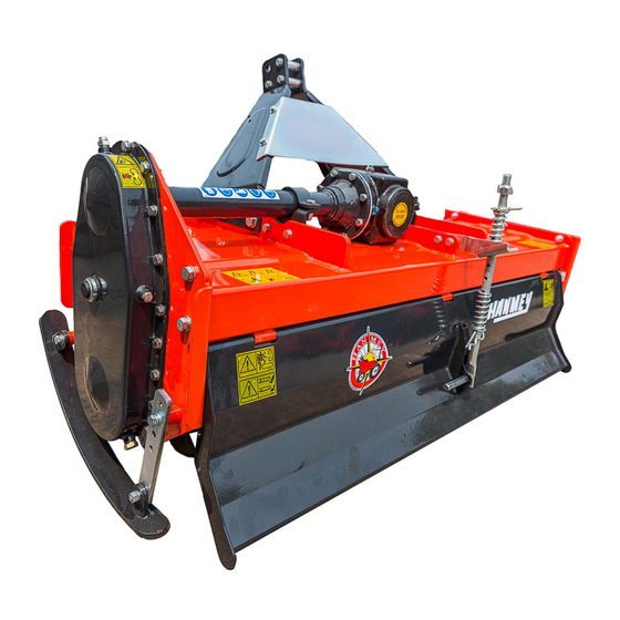
Page 8: Universal Coupling Assy
Fig.1 The side sketch of rotary tiller 2.1 Universal coupling assy The universal coupling consists of universal joint head, universal joint head for male shaft, the universal joint head for female shaft and joint cross. There are rings on the both ends of joint cross to avoid the movement of joint cross, and there is also a grease hole on the joint cross and the needle bearing can be well lubricated if you inject grease into it frequently. -
Page 9: Side Gearbox Assy
just move the pinion forward when you do it. Adjustment of the bearing axial clearance on the second shaft when the axial displacement was occurred very distinctly on the second shaft, you must adjust it in time as following steps: First, loosen washer and screw down the locknut, then adjusts the displacement of the bearing on the second shaft until there was no distinct axial movement and easy to rotate the shaft. -
Page 11: Chapter Ⅲ Methods Of Operating
Chapter Ⅲ Methods of operating 3.1 Installation of headstock with the main body Before being put in the container, the equipment is parted with the main body. The users refer to fig.2 simply to fix it on the main body with the bolts in the affix pouch. -
Page 12: Adjustment Before Working
3.4 Adjustment before working 1. Adjustment of horizontal level Put it down to make the blade tips near to ground, observe that the height between the right and left blade tips and the ground is same or not. If not, it is necessary that the right linkage arm of tractor be adjusted to level off the blade shaft, which ensures the uniformity of working depth. -
Page 13: Starting Of The Tiller
the empty time in turn land will be longer, the efficiency be less, the repeat times of idle motion be more, tne mud depth be longer. The flat tillage in the medium and small fields refer to in land plowing. Fig.5 In land plowing 3.6 Starting of the tiller First, filling with gear oil in the gearbox and the side chain box, injecting grease to the crosshead and the bearing seat of the blade shaft. -
Page 14: Selecting Of Forward Speed
depth at the same time. 3.7 Selecting of forward speed The selecting principle of tiller forward speed: the tractor cannot overload constantly; the performance of breaking soil meet the needs of agriculture requirement, furrow bottom and the soil surface are smooth. Not only be tillage quality ensured, but also the rated power of tractor be made good use of, and the purpose of rising work efficiency must be attained. -
Page 15: Chapter Ⅳ M A I N T E N A N C
Chapter Ⅳ Maintenance To ensure that the tiller works properly, higher efficiency and prolonging the serve life, it is important that maintenance must be done properly. 4.1 Daily maintenance (after 10 hours operating) 1. Check, tighten up all of the joint bolts and nuts, tighten them up or replace them if necessary. 2. -
Page 16: L U B R I C A T I O N S I T E
6. Check the blades to see if there is crack, wear and tear on them, or loss. It must be replaced or added if necessary. 7. Check the blade holder, replace or repair them if necessary. 8. Repair the cover and the trailing bar. 9. - Page 17 Store the machine in a dry, level area. Support the frame with planks if require. 4.6 Operation After Storage Before the machine is started up, check the following items regularly: Check oil level and add it if not enough. Check and tighten all screws and nuts; Check the regulated state of the machine.
-
Page 18: Chapter Ⅴ C O M M O N B R E A K D O W N A N D I T S F I X I N G M E T H O
Chapter Ⅴ Common breakdown and its fixing method Breakdowns Cause of breakdown Removing method Adjust the horizontal level of Rotary tiller failed horizontal level Universal coupling the tiller inclined too much One side sway chain of tractor is too Adjust the chain short Direction mistaken Re-assemble correctly... - Page 19 Cultivator shaft twined with grass or hold Clear away grass or soil soil seriously Blade run foul of stone so that it suffers Clear away the stone from the too much force field Blade assembled on opposite direction Blade slot injured Assemble the blades correctly so that it suffers too much force Rotary tiller fallen down the soil sharply...
-
Page 20: Chapter Ⅵ N O T E S F O R S A F E T
Chapter Ⅵ Notes for safety 1. The operators must understand the operating characteristics and notes for safety. 2. Check the rotary tiller overall, it cannot be used until the technical condition is normal. 3. The angle of universal coupling is not more than ±10°when it is operating, and is not more than 30° when the tractor turns a corner in the field. You must dismantle the universal coupling when long-distance transporting. - Page 21 Parts List...
- Page 22 Item SYS NO. Parts No. Name 803140004 1G-90.01.001 (90) gear box 803150003 1G-100.01.001 (100) gear box 803160002 1G-105.01.001 (105)gear box 803170002 1G-125.01.001 (125)gear box 803180002 1G-135.01.001 (135)gear box 803190150 1G-150.01.001 (150)gear box 803220002 1G-180.01.001 (160-180)gear box 803230004 1G-180.01.001A1 (180) Canada gear box 803140008 1G-125.01.001 (125-M)gear box...
- Page 23 GB3452.1-G-28X3.5 510013218 O sealing 12-1 803140001 1G-90.00.011-2 blade shaft 12-2 803150002 1G-100.00.011-2 blade shaft 12-3 803160003 1G-105.00.011-2 blade shaft 12-4 803170004 1G-125.00.011-2 blade shaft 12-5 803180005 1G-135.00.011-2 blade shaft 12-6 803190006 1G-150.00.011-2 blade shaft 12-7 803200007 1G-160.00.011-2 blade shaft 12-8 803210239 1G-170.00.011-2 blade shaft...
- Page 24 501010778 GB5782-M16X55 half thread bolt (150) 21-1 803190111 1G-150.00.017 suspension left-side plate for IGN125 and 135 (180) 21-2 803220112 1G-180.00.017 suspension left-side plate for IGN180 506010059 GB97.1-16 plain washer 506030039 GB93-16 spring washer 503010049 GB6170-M16 hex nut 703140006 MZ105.130 spacer bush 501011126 GB5783-M12X30 screw bolt...
- Page 25 32-4 703190125 1G-150.00.102 (150-160) right blade for IGN150 and IGN160 32-5 703190125 1G-150.00.102 (170-180) right blade for IGN170 and IGN180 33-1 803140003 1G-90.00.014 right-side plate 33-2 803190051 1G-150.00.014 right-side plate 33-3 803230001 1G-150.00.014A right-side plate 33-4 806560002 1G-150.00.014T right-side plate 803190127 1G-150.00.104 bearing cover plate...
- Page 26 703190143 1G-150.00.109A V press plate 501011143 GB5783-M14X45 screw bolt 506010057 GB97.1-12 plain washer 508050061 GB91-3X28 cotter pin 54-1 703140130 1G-90.00.105 (90-L960) back shield shaft 54-2 703150131 1G-100.00.105 (100-L1060)back shield shaft 54-3 703160132 1G-105.00.105 (105-L1110)back shield shaft 54-4 703170133 1G-125.00.105 (125-L1310)back shield shaft 54-5 703180134 1G-135.00.105...
- Page 27 55-10 805730031 1G-125-012-2A back shield (125 intermediate gear box) 55-11 805740032 1G-135-012-2A back shield (135 intermediate gear box) 55-12 805750033 1G-150-012-2A back shield (150 intermediate gear box) 55-13 805760034 1G-180-012-2A back shield (180 intermediate gear box) 703190232 1G-150.00.147 hexagonal steel handle shank 703340017 ZL-25.104 big R pin...
- Page 28 64-9 803220065 1G-180.00.015 (180)top cover plate 64-10 805730066 1G-125.00.015(中) top cover plate(125 intermediate gear box) 64-11 805740067 1G-135.00.015(中) top cover plate(135 intermediate gear box) 64-12 805760069 1G-180.00.015(中) top cover plate(180 intermediate gear box)
- Page 29 Gearbox :...
- Page 30 Item SYS NO. Parts No. Name 803190004 Whole gear box 70319019 1G-150.01.118 gear box shell 51002041 CFW-40X80X12 seal ring 50606019 GB893.1-80 circlip 51101641 GB297-30208 conical roller bearing 70319019 1G-150.01.117-1 input shaft 70319020 1G150.02-04 (90-150)small cone gear 70319020 1G150.04-08 (90-150)big cone gear 70321000 (160-180)...
- Page 31 Transmission Item SYS NO. Parts No. Name 70319019 1G-150.01.118 transmission box 70314018 1G-90.01.109 (L504)transmission shaft 70315018 1G-100.01.109 (L537) transmission shaft 70316019 1G-105.01.109 (L554) transmission shaft...
- Page 32 70317019 1G-125.01.109 (L620.5) transmission shaft 70318019 1G-135.01.109 (L656) transmission shaft 70319019 1G-150.01.109 (L706) transmission shaft 70322019 1G-180.01.109 (L806) transmission shaft 80314016 (90-L316) 1G-90.01.013A transmission shaft sleeve 80315016 (100-L349) 1G-100.01.013A transmission shaft sleeve 80316016 (105-L366) 1G-105.01.013A transmission shaft sleeve 80317016 (125-L432.5) 1G-125.01.013A transmission shaft sleeve 80318016...
- Page 33 51002038 CFW-40X70X12 FB oil seal 51101649 GB297-30308 conical roller bearing 80314000 1G-90.01.011 (90-105)left side plate 80319015 1G-150.01.011 (125-180)left side plate 50101112 GB5783-M12X35 screw bolt 70319018 1G-150.01.106-2 intermediate gear shaft 50606019 GB893.1-100 checking ring 51102265 GB276-6309 deep groove ball bearing 51002041 GB13871-FB-55X80X8 FB oil sealing 70319018...
Need help?
Do you have a question about the IGN Series and is the answer not in the manual?
Questions and answers
I have smoke come out of the machine ,would that be the clutch