Advertisement
Quick Links
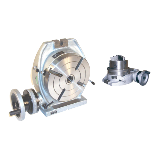
Operating Instructions & Parts Manual
Horizontal & Vertical Rotary Tables
Dividing Plates
Operation and Parts Manual
221 Series Horizontal/Vertical Rotary Tables
* Fill with OIL-Prior to Use *
21 Industrial Ave • Upper Saddle River, NJ. 07458
Tel: (201)962-7373 • Fax: (201)962-8353
E-Mail:
info@phase2plus.com
Web Site: http://www.phase2plus.com
Pg. 1
Advertisement

Summary of Contents for phase II+ 221 Series
- Page 1 Operating Instructions & Parts Manual Horizontal & Vertical Rotary Tables Dividing Plates Operation and Parts Manual 221 Series Horizontal/Vertical Rotary Tables * Fill with OIL-Prior to Use * 21 Industrial Ave • Upper Saddle River, NJ. 07458 Tel: (201)962-7373 • Fax: (201)962-8353 E-Mail: info@phase2plus.com...
- Page 2 Operating Instructions & Parts Manual Horizontal & Vertical Rotary Tables Dividing Plates Operating Instructions & Parts Manuals Please read and save these instructions. Read carefully before attempting to assemble, install, operate or maintain the product described. Protect yourself and others by observing all safety information. Failure to comply with instructions could result in personal injury and or property damage! Retain instructions for future reference.
- Page 3 Operating Instructions & Parts Manual Figure 1 - Dimensions Dimensions Refer to Figure 1. NOTE: All dimensions are in inches. 4” Table 6” Table 8" Table 10" Table 12" Table 16” Table 221-304 221-306 221-308 221-310 221-312 221-316 4.92 9.53 11.2 12.900 16.125...
-
Page 4: Operation
Operating Instructions & Parts Manual Operation Refer to Figures 4 thru 8. Rotary Table 1. Always rotate handwheel (Ref.No.46) clockwise. This will eliminate any backlash in the worm gear. If handwheel is rotated past desired position, rotate handwheel one full turn counterclockwise and then rotate handwheel clockwise to desired position. -
Page 5: Maintenance
Operating Instructions & Parts Manual To assemble the dividing plate attachment to the rotary table, remove handwheel (Ref.No.46). Bolt the required plate to the collar using 4 screws (Figure 3, Ref No. 3). Slide the sector (Figure 3, Ref. No 4) over the worm shaft and eccentric sleeve (Ref.Nos.31 and 37) with the sector screw exposed. - Page 6 Operating Instructions & Parts Manual Keep rotary table clean of dirt or chips. Lubrication Before putting into use, fill base cavity with oil using the oil zerts on base, table and oil plug(Ref No. 11). Unscrew oil Plug prior to lubrication. Before every shift of operation fill adequate oil through oil zerts and oil plug. LUBRICATE WITH LIGHT DUTY HYDRAULIC FLUID OR SPINDLE OIL.
- Page 7 Operating Instructions & Parts Manual Figure 3-Replacement Parts Illustration for Model 241-101 Figure 3 – Replacement Parts Illustration for 241-101 Dividing Attachment Replacement Parts List for Dividing Attachment Reference No. Description Part No. Dividing plate with 34-41 and 43-61 holes 9283 Dividing plate with 46-53 and 54-66 holes 9284...
- Page 8 Operating Instructions & Parts Manual Please Provide following information: Stock Number Serial Number (if Any) Part descriptions and number as shown in parts list Figure 4-Replacement Parts For 221-306 6” Rotary Table Pg. 8...
- Page 9 Operating Instructions & Parts Manual Replacement Parts for Model 221-306 9205 1 9225 Part Base Locating key Ref. No. Description Ref. No. Description Part No. Qty 9206 1 Table 5 x 6mm Set Screw 9207 1 9226 Taper Sleeve Threaded Pin 9227 6 x 16mm Socket Head Block...
- Page 10 Operating Instructions & Parts Manual Exploded View Drawing of 221-308 8” Horizontal and Vertical Rotary Table Figure 5 – Replacement Parts Illustration for 221-308 8” Rotary Table Pg. 10...
- Page 11 Operating Instructions & Parts Manual Replacement Parts for Model 221-308 9205 1 9225 2 Ref. Part Ref. Part Base Locating Key Description Description 9206 1 Table 5-0.8x8mm Set Screw 9207 1 9226 1 Taper Sleeve Threaded Pin ∗ 9227 1 6-1.0x22mm Socket Block Head Bolt...
- Page 12 Operating Instructions & Parts Manual Please Provide following information: Stock Number Serial Number (if Any) Part descriptions and number as shown in parts list Exploded View Drawing of 221-310 10” Horizontal & Vertical Rotary Table Figure 6 – Replacement Parts Illustration for 221-310 10” Rotary Table Pg.
- Page 13 Operating Instructions & Parts Manual Replacement Parts List for Model 221-310 Ref. Part Ref. Part 9248 1 9225 2 Base Locating Key Description Description 9249 1 Table 5-0.8 x 8mm set screw 9250 1 9261 1 Taper Sleeve Threaded pin ∗...
- Page 14 Operating Instructions & Parts Manual Please Provide following information: Stock Number Serial Number (if Any) Part descriptions and number as shown in parts list Exploded View Drawing of 221-312 12” Horizontal & Vertical Rotary Table 221-312 12” Rotary Table Figure 7-Replacement Parts Illustration for Pg.
- Page 15 Operating Instructions & Parts Manual Replacement Parts List for 221-312 9265 1 9278 2 Part Part Base Locating Key Description Description 9266 1 Table 5-0.8 X 8mm Set Screw 9267 1 9261 1 Taper Sleeve Threaded Pin ∗ 9262 1 8-1.25 X 28mm Socket Block Head Bolt...
- Page 16 Operating Instructions & Parts Manual Exploded View Drawing of 221-316 16” Horizontal & Vertical Rotary Table Figure 8-Replacement parts Illustration for 221-316 16” Rotary Table Pg. 16...
- Page 17 Operating Instructions & Parts Manual Replacement Parts List for 221-316 9265 1 9278 2 Part Part Base Locating Key Description Description 9266 1 Table 6 X 12mm Set Screw 9267 1 9261 1 Taper Sleeve Threaded Pin ∗ 9262 1 10 x 25mm Socket Block Head Bolt...
-
Page 18: Troubleshooting Chart
Operating Instructions & Parts Manual Troubleshooting Chart Symptom Possible Cause(s) Corrective Action Handwheel rotates: 1.Key(Ref.No.32) is missing 1. Insert Key Table does not rotate 2. Worm Shaft disengaged 2. Engage worm shaft (see operation) Handwheel will not rotate 1. Hold-down clamps are 1. - Page 19 Operating Instructions & Parts Manual Dividing Plate Chart Revision (08/2007) The dividing chart shown in this operation manual was found to have a few minor errors. The charts on the following pages will rectify any errors shown previously as well as give 100% coverage of every possible division using the standard dividing plate set.
- Page 20 Operating Instructions & Parts Manual Pg. 20...
- Page 21 Operating Instructions & Parts Manual Pg. 21...
-
Page 22: Mounting Instructions
Operating Instructions & Parts Manual Rotary Table/Lathe Chuck Adapter Plates 221-304 221-306 221-308 221-310 221-312 221-316 Table± Size 4” Table 6” Table 8” Table 10” Table 12” Table 16” Table Plate 221-354 221-356 221-358 221-360 221-362 221-366 Lathe 559-110 559-112 559-113 559-114 559-115... - Page 23 Operating Instructions & Parts Manual Worm Gear / Eccentric Sleeve Adjustment for H/V Rotary Tables First Loosen Handle A for the eccentric sleeve lock and proceed to unscrew Bolt B. Screw clockwise the Limiting Bolt A to adjust the mesh of the worm gear to the table top gear.
- Page 24 Operating Instructions & Parts Manual Main Headquarters: U.S.A Phase II Machine & Tool, Inc. 21 Industrial Ave Upper Saddle River, NJ. 07458 USA Tel: (201) 962-7373 Fax: (201) 962-8353 General E-Mail: info@phase2plus.com BEIJING, CHINA Phase II Measuring Instruments (Beijing) Ltd. Room 301, Bldg 2 Qing Yuan Xi Li, Haidian District, Beijing 100192,China Tel:+86-10-59792409...
Need help?
Do you have a question about the 221 Series and is the answer not in the manual?
Questions and answers