Table of Contents
Advertisement
Quick Links
Advertisement
Table of Contents

Related Manuals for Helm HM-1734-WM

Summary of Contents for Helm HM-1734-WM
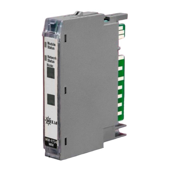
- Page 1 Helm Instrument Company, Inc. 361 West Dussel Drive Maumee, Ohio 43537 USA 419/ 893-4356 Fax: 419/ 893-1371 www.helminstrument.com Point I/O Strain Gage Input Module Model HM-1734-WM Instruction Manual Rev. 4.18 June, 2021 Force Measurement and Control Solutions...
- Page 2 HM1734-WM STRAIN GAGE INPUT MODULE This Series C product can be used with DeviceNet and PROFIBUS adapters. It can be used with Ethernet/IP and Ethernet adapters using RSLogix 5000, version 11 (or higher) software. Important User Information Because of the variety of uses for the products described in this publication, those responsible for the application and use of these products must satisfy themselves that all necessary steps have been taken to assure that each application and use meet all performance and safety requirements, including...
- Page 3 HM1734-WM STRAIN GAGE INPUT MODULE Identifies information about practices or ATTENTION circumstances that can lead to personal injury or death, property damage, or economic loss. Identifies information that is critical for IMPORTANT successful application and understanding of the product...
-
Page 4: Environment And Enclosure
HM1734-WM STRAIN GAGE INPUT MODULE Environment and Enclosure ATTENTION This equipment is intended for use in a Pollution Degree 2 industrial environment, in overvoltage Category II applications (as defined in IEC publication 60664-1), at altitudes up to 2000 meters without derating. This equipment is considered Group 1, Class A industrial equipment according to IEC/CISPR Publication 11. -
Page 5: Explosion Hazard
HM1734-WM STRAIN GAGE INPUT MODULE EXPLOSION HAZARD WARNING Do not disconnect equipment unless power has been removed or the area is known to be nonhazardous. Do not disconnect connections to this equipment unless power has been removed or the area is known to be nonhazardous. - Page 6 HM1734-WM STRAIN GAGE INPUT MODULE Installing the Mounting Base To install the mounting base on the DIN rail, proceed as follows. 1. Position the mounting base vertically above the installed units adapter, power supply or existing module. 2. Slide the mounting base down allowing the interlocking side pieces to engage the adjacent module or adapter.
- Page 7 Be sure that power is removed or the area is nonhazardous before proceeding. Some non-Helm load cell summing devices may be incompatible due to signal trimming. Please contact Helm support for verification at 704-942-4710.
-
Page 8: Removing A Mounting Base
HM1734-WM STRAIN GAGE INPUT MODULE Removing a Mounting Base To remove a mounting base, you must remove any installed module, and the module installed in the base to the right. Remove the removable terminal block (if wired). 1. Unlatch the RTB handle on the I/O module. 2. -
Page 9: Run Mode
Useful when troubleshooting load cell wiring or other failures. TARE CH1/CH2 Sets A/D value to zero. READ ADTRIM BIT (HELM Factory setting only). SET-TO-CH1 Bit Used for one channel operation where a faster sample speed is required. 1 = 2msec (max speed) - Page 10 HM1734-WM STRAIN GAGE INPUT MODULE REQUIRED CONTROLLER TAGS CH1/CH2 SCALE SET / REFERENCE WEIGH VALUE LOCAL : 2 : C, DATA[0] LOCAL : 2 : C, DATA[3] Full scale setting for CH1, CH2 Value is determined by capacity of load cell and by resolution required. Example: 10KG = 10,000 GET WEIGH VALUE CH1, CH2 GET_WEIGH_CH1...
-
Page 11: Troubleshooting With The Indicators
HM1734-WM STRAIN GAGE INPUT MODULE Troubleshooting with the Indicators Module Status: No power applied to device. Green Device operating normally. Flashing Green Device needs commissioning due to configuration missing, incomplete or incorrect. Flashing Red Recoverable fault. Unrecoverable fault. May require device replacement. -
Page 12: Setup Procedure
HM1734-WM STRAIN GAGE INPUT MODULE Setup Procedure A complete listing of a sample ladder logic program is included at the back of this manual. Examples shown here are for reference. All values are 0 (default) on initial start-up. This means that all alarms are disabled. You must make the following adjustments for proper operation: ... - Page 13 LED indicators 2 LEDs for Power and Alarm Recommended Cable Strain Gage Cable (Helm part number 6117) Operating Temperatures 0°C to 60°C (32°F to 140°F) Emissions CISPR 11 Group 1, Class A...
- Page 14 HM1734-WM STRAIN GAGE INPUT MODULE SETTING UP HM1734WM MODULE USING 1734-AENT/A on Ethernet/IP Step #1 Add module to project as following: HM1734WM MODULE PROPERTIES General Tab Settings Connection Tab Settings *RPI rate cannot be faster than 4ms.
- Page 15 HM1734-WM STRAIN GAGE INPUT MODULE Step #2 Open “HM1734_WM_AOP_REV418. ACD” Copy HM1734WM_main routine Open project Paste HM1734WM_main routine Check program tag here should be as Example...
-
Page 16: Output Bits
HM1734-WM STRAIN GAGE INPUT MODULE Data Map for HM1734-WM on Ethernet/IP OUTPUT BITS Local:2:O.Data[0].0 cal mode Local:2:O.Data[0].1 run mode Local:2:O.Data[0].2 ch1 clear tare Local:2:O.Data[0].3 ch1 tare Local:2:O.Data[0].4 ch1 set adtrim Local:2:O.Data[0].5 read adtrim Local:2:O.Data[0].6 ch2 clear tare Local:2:O.Data[0].7 ch2 tare Local:2:O.Data[1] Local:2:O.Data[1].0 ch2 set adtrim... -
Page 17: Controller Tags
HM1734-WM STRAIN GAGE INPUT MODULE Data Map for HM1734-WM on Ethernet/IP CONTROLLER TAGS get_weight_ch1 2792725 Decimal DINT get_weight_ch2 2794308 Decimal DINT Local:2:C.Data[0] 5000 Decimal ch1 scale Local:2:C.Data[1] 2000 Decimal ch1mv_v Local:2:C.Data[2] 5000 Decimal ch2 scale Local:2:C.Data[3] 2000 Decimal ch2 mv_v Set or Change Configuration Data: ... - Page 18 HM1734-WM STRAIN GAGE INPUT MODULE HM1734-WM AOP rev418. ACD CALIBRATING WITH KNOWN LOAD (AUTO-CAL) Ver. 4.18 1) Set known weight for channel at scale parameter. 2) Tare-0 (with no weight on cell/scale). 3) Set module to AUTOCAL mode (BIT). 4) Apply known load (test weight) to load cells/ scale. 5) Set AUTO TUNE BIT on for CH1 (CH2 if applicable).
- Page 19 HM1734-WM STRAIN GAGE INPUT MODULE HM1734-WM ADDON rev3. ACD...
- Page 20 HM1734-WM STRAIN GAGE INPUT MODULE HM1734-WM ADDON rev3. ACD HM1734WM:1:O.Data[0].0 BOOL cal mode HM1734WM:1:O.Data[0].1 BOOL run mode HM1734WM:1:O.Data[0].2 BOOL ch1 clear tare HM1734WM:1:O.Data[0].3 BOOL ch1 tare HM1734WM:1:O.Data[0].4 BOOL ch1 adtrim HM1734WM:1:O.Data[0].5 BOOL read adtrim HM1734WM:1:O.Data[0].6 BOOL ch2 clear tare HM1734WM:1:O.Data[0].7 BOOL ch2 tare HM1734WM:1:O.Data[1].0...
- Page 21 HM1734-WM STRAIN GAGE INPUT MODULE CALIBRATING WITH KNOWN LOAD (AUTO-CAL) Ver. 4.17 1) Set known weight for channel at REF WEIGH VALUE. 2) Tare-0 (with no weight on cell/scale). 3) Apply known load (test weight) to load cells/ scale. 4) Set AUTO CAL ENABLE BIT on for CH1 (CH2 if applicable). 5) To ensure accuracy repeat the steps above.
- Page 22 HM1734-WM STRAIN GAGE INPUT MODULE...
- Page 23 HM1734-WM STRAIN GAGE INPUT MODULE Helm HM-1734-WM 4-Wire Weigh Cell Connection...
- Page 24 HM1734-WM STRAIN GAGE INPUT MODULE...
- Page 25 Bulleted lists such as this one provides information, not procedural steps. Numbered lists provide sequential steps or hierarchical information. Product Support Contact your Helm representative or call Helm direct at 419-893-4356: sales and order support product technical training warranty support ...
Need help?
Do you have a question about the HM-1734-WM and is the answer not in the manual?
Questions and answers