Table of Contents
Advertisement
Quick Links
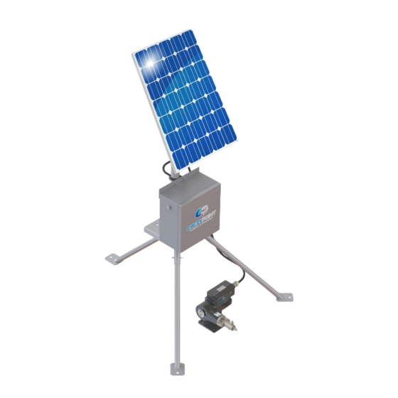
Series FXS Solar Injection System
Operating Manual
Series FXS
Solar Injection System
Operating Manual
CheckPoint Headquarters
CheckPoint UK
CheckPoint Systems Pte Ltd
CP Pumps & Systems FZE
21356 Marion Lane
C2/C3 Lombard Centre
21 Toh Guan Road East
Unit AA08, LIU 10
Mandeville, Louisiana 70471
Kirkhill Place, Kirkhill Industrial Estate
#04-17 Toh Guan Centre
Jebel Ali South | PO Box 262131
United States of America
Dyce, Aberdeen AB21 0GU Scotland
Singapore 608 609
Dubai | UAE
+1 (504) 340-0770
+44 (0)1224 775205
+65 6261 7687
+971 (4) 8806278
CP/MAN-PRD-008
REV. 02
EFF. DATE: 07/06/2022
Page 1 of 35
Advertisement
Table of Contents

Summary of Contents for Checkpoint FXS Series
- Page 1 Operating Manual Series FXS Solar Injection System Operating Manual CheckPoint Headquarters CheckPoint UK CheckPoint Systems Pte Ltd CP Pumps & Systems FZE 21356 Marion Lane C2/C3 Lombard Centre 21 Toh Guan Road East Unit AA08, LIU 10 Mandeville, Louisiana 70471...
-
Page 2: Table Of Contents
Series FXS Solar Injection System Operating Manual TABLE OF CONTENTS PUMP INSTALLATION Process Design & Setup ........................... 5 Connecting the Chemical Supply ......................8 Connecting the Solar Power Supply ....................10 2. PUMP OPERATION Bleeding/Priming the Injector Head ....................11 Setting and Adjusting the Pump Delivery Volume ................ - Page 3 Series FXS Solar Injection System Operating Manual 7. TROUBLESHOOTING Pump Runs, but Chemical does not Discharge at the Correct Rate ..........32 Pump Does Not Stroke .......................... 33 Pump is Excessively Noisy ........................33 Chemical Leakage from Packing ......................33 Other Problems ............................
- Page 4 Failure to correctly install and maintain the product is the primary cause of premature failure and voids the product warranty. NOTE: This IOM applies to the CheckPoint Solar FXS Chemical Injection Pumps, part number FXS2- (FXS Code)-(Injection Assembly) for Series 1250 head, and FXS5-(FXS Code)-(Injection Assembly) for Series 1500 head.
-
Page 5: Pump Installation
CheckPoint packages are available for FXS Series pumps that contain all necessary components indicated within the PACKAGE LIMIT in Figure 1. CheckPoint can supply packages that contain ALL components in Figure 1, including the tank, mounted on a single skid with or without full leak containment. - Page 6 CheckPoint recommends all components shown above to maximize productivity and life of the pump in typical field or plant use. CheckPoint is available to answer all of your process questions or to help design and build a package system utilizing components appropriate for your application.
- Page 7 Series FXS Solar Injection System Operating Manual 1.1.7 CheckPoint ships the FXS pump with a pre-drilled floor stand, and this is the recommended method for mounting the pump. The pump may be mounted to a skid or other surface in a number of ways;...
-
Page 8: Connecting The Chemical Supply
1.2.2 Connect the chemical suction line to the suction check valve on the pump head (See illustrations in CheckPoint’s Series FXS Solar Injection System Parts List document, available upon request or for download at cppumps.com). The suction check valve is a 1/4" MNPT for the Series 1250 and 1/2" MNPT for the Series 1500. - Page 9 Series FXS Solar Injection System Operating Manual CAUTION: The Solar FXS Series 1250 pump universal chemical head is rated for a maximum working pressure of 7,500 PSIG, and the 1250 1/8” head is rated for 12,000 PSIG. The FXS Series 1500 pump universal chemical head is rated for a maximum working pressure of 7,500 PSIG, and the 1500 HP head is rated for 15,000 PSIG.
-
Page 10: Connecting The Solar Power Supply
Series FXS Solar Injection System Operating Manual Connecting the Solar Power Supply FIGURE 2: ELECTRICAL INSTALLATION LOCATION 1.3.1 The solar powered electric motor must be connected in accordance with all local regulations, including overload protection. FXS Solar pumps are equipped with Class 1, Div 2 (Group A, B, C, D) 1/5 HP motors. -
Page 11: Pump Operation
Series FXS Solar Injection System Operating Manual PUMP OPERATION Bleeding/Priming the Injector Head NOTE: Prior to initial pump operation, ensure the suction check valve is connected to adequate chemical supply per Section 1.2. 2.1.1 The bleed screw on the Series 1500 injection head is fitted with a 1/8" FNPT connector to allow the user to tube chemical used in the bleeding process to the proper containment area or vessel. -
Page 12: Setting And Adjusting The Pump Delivery Volume
Figure 3. 2.2.3 Adjusting the RPM during operation will not damage the FXS Series pump or motor. 2.2.4 The speed should only be set from 10 to 100%. -
Page 13: Setting The Pump Stroke Rate
2.3.1.4 Ensure that the CheckPoint pump is running. Take note of the level of chemical in the gauge, using the appropriate scale for your preferred pump output volume units. Usually, the gauge will show liters on one scale and quarts or gallons on the other. - Page 14 Series FXS Solar Injection System Operating Manual 2.3.1.7 Write down the amount of time in seconds and the final gauge reading, and close the gauge fill valve. NOTE: In cases where the chemical flow rate is extremely low, you may need to time for longer than one minute to allow an adequate amount of chemical to move out of the gauge.
- Page 15 Series FXS Solar Injection System Operating Manual 2.3.2.1 Using your desired chemical flow rate, calculate an Unrated Stroke Rate (USR). Figure 4 contains volume factor using Series 1250. Figure 4A contains volume factor using Series 1500. Figure 5 contains basic conversions to assist you. Figure 6 displays the volume de-rating percentage vs. discharge pressure. UNRATED STROKE RATE (USR) (STROKES/MIN) = ×...
- Page 16 Series FXS Solar Injection System Operating Manual FIGURE 6: VOLUME DE-RATING PERCENTAGE VS. DISCHARGE PRESSURE 2.3.2.2 Volume per stroke decreases as the discharge pressure rises. It is necessary to apply a Volume De- Rating Percentage (VDP) to the Unrated Stroke Rate (USR). The VDP is based on the expected discharge pressure the pump will experience.
-
Page 17: Packing Adjustment
2.4.2 To adjust the packing, use a CheckPoint T55-101 packing adjuster, which is specifically designed for this purpose. If one is not available, you may order one at no charge directly from CheckPoint. In an emergency or if time is short, a 6" length of ¼" OD tubing or a metal rod may be used. -
Page 18: Packing Replacement
2.5.5 Unscrew and remove the packing nut, using 1/4" tubing or a packing nut tool. A packing nut tool is available at no charge from CheckPoint. For all sizes other than 3/16", proceed to step 2.5.7. 2.5.6 Using the access hole where the suction check valve was located, push out the packing and sleeve with a punch or screwdriver. - Page 19 Series FXS Solar Injection System Operating Manual FIGURE 8: TYPICAL PACKING INSTALLATION TOP RING – PEEK FEMALE ADAPTER RING – TFM BACKUP RING – TFM ELASTOMER – (FFKM, VITON, BUNA) MALE ADAPTER RING – TFM NOTE: When replacing adjustable packing, always install the packing rings exactly as they are shipped.
-
Page 20: Pump Maintenance
3.1.1 Startup The Solar FXS Series pumps are delivered without a filled reservoir. Prior to startup, fill the FXS drive housing using 2 ounces (60mL) of SAE rated 5W-30 motor oil. CheckPoint recommends using Mobil 1 Fully Synthetic 5W-30 for extended life. -
Page 21: Fuses
Series FXS Solar Injection System Operating Manual FUSES General Information Fuses have been integrated into the control panel to protect the solar panel and charge controller should a short circuit occur. Further the motor fuse is sized to limit the draw of the motor to protect the system. If the motor fuse ever blows, this is normally a sign that the pump is working beyond the intended system capability range. -
Page 22: Solar Support Components
SOLAR SUPPORT COMPONENTS Battery Bank 5.1.1 CheckPoint uses 100Ah and 110Ah sealed lead-acid (SLA) batteries. No maintenance is required for these batteries; however, disconnecting the terminal cables when the solar pump system is not in use will help to extend the life of the battery bank. -
Page 23: Charge Controller
Series FXS Solar Injection System Operating Manual 5.1.3 Batteries are approved for transport by air, D.O.T., I.A.T.A., F.A.A., and C.A.B. certified. U.L. recognized under file number MH 20567. NOTE: Do not store or install batteries in sealed containers. Charge Controller FIGURE 12A: CHARGE CONTROLLER •... - Page 24 Series FXS Solar Injection System Operating Manual FIGURE 12B: CHARGE CONTROLLER 5.2.3 LCD Graphic Indicators FIGURE 13: LCD GRAPHIC INDICATORS LCD Symbol Description Digital parameter Shows measurement in numerical format (0 - 9) Charge Indicator When visible, indicates that the solar panel is charging the battery When blinking, battery is fully charged and in ‘float’...
- Page 25 Series FXS Solar Injection System Operating Manual 5.2.4 LCD Interface Cycle FIGURE 14: LCD INTERFACE CYCLE 5.2.5 Interface Definitions The SOLR0008-021 has six different graphical interfaces. Each interface contains different information. The Main Interface displays the current state of the Load, PV charging, Load discharging, battery capacity, and overall system working condition as shown below.
- Page 26 Series FXS Solar Injection System Operating Manual 5.2.7 Float Charge Interface The value displayed in this interface is the float charge voltage setting. When the battery reaches the set voltage, the controller will maintain this value to prevent the battery from overcharging. NOTE: To change the float charge setting, press the ‘CYCLE’...
- Page 27 Series FXS Solar Injection System Operating Manual 5.2.9 Low Voltage Disconnect (LVD) Interface The value displayed in this interface is the Low Voltage Disconnect protection voltage set for the controller. If the battery voltage is lower than the set protection voltage, the controller will automatically disconnect the load to prevent the battery from over-discharging.
- Page 28 Series FXS Solar Injection System Operating Manual Value Mode Function Normal (Default) Load is supplied continuous power Load is supplied power at nighttime and continues working for the specified duration (in hours). For example, if the Load 1h - 23h Timed Control Control Value is set to 2h, then the load will be turned on at night time and remain on for a period of 2 hours.
- Page 29 Series FXS Solar Injection System Operating Manual 5.2.12 Error Conditions - Low Voltage Protection If the battery voltage is lower than the protection voltage (Section 4.2.9), the controller will enter the low voltage protection state and the load will be disconnected. The use of solar panels or an alternate charger is required to charge the battery to the recovery level (Section 4.2.8).
- Page 30 Should the solar package need to be moved to a different application or location, please contact your CheckPoint representative, to ensure that your solar support equipment is properly sized. 5.3.3 Correct alignment is important to properly maintain battery charge levels. Follow local guidelines to determine optimal direction and tilt of solar array for optimal performance.
-
Page 31: Flow Information
FLOW INFORMATION Flow Charts 6.1.1 The CheckPoint Series Series FXS Solar Injection System assembly has four standard configurations designed to meet specific application requirements: a single panel, single battery system, a single panel, dual battery system, a dual panel single battery system and a dual panel, dual battery system. Your CheckPoint representative will help to determine the correct system for your application and geographic location. -
Page 32: Troubleshooting
NOTE: CheckPoint FailSafe check valves do not need replacement when they do not check properly. A simple rebuild kit is available to replace the O-rings, which should correct all but the most severe check problems. -
Page 33: Pump Does Not Stroke
7.4.1.1 Chemical may be attacking packing elastomer material The packing will appear swollen or badly damaged once removed from the packing gland if it is being attacked by the chemical. Contact CheckPoint or your authorized CheckPoint distributor. If the chemical has recently been changed, or if the pump has just been placed in service, there is a good chance that new packing materials are needed to do the job. -
Page 34: Other Problems
CheckPoint product. 7.5.3 After you repair your CheckPoint pump, it should perform as well as it did when it was new If it doesn’t, call us so that we can determine what we can do to restore the pump to “like-new”... -
Page 35: Appendix
Series FXS Solar Injection System Operating Manual APPENDIX CP/MAN-PRD-008 REV. 02 EFF. DATE: 07/06/2022 Page 35 of 35... - Page 36 In the appropriate insolation factor column, find a maximum flow rate and discharge pressure value that are both equal to or greater than the application requirement. • Confirm that the minimum flow rate of that plunger is equal to or less than the application requirement. • Please contact CheckPoint for assistance or to discuss a customized solution. • CP/MAN-PRD-008 REV. 02...
Need help?
Do you have a question about the FXS Series and is the answer not in the manual?
Questions and answers