
Subscribe to Our Youtube Channel
Summary of Contents for North America Traffic PTL 2.4 Series
- Page 1 PTL 2.4x Portable Traff ic Signal Manual THE LEADER IN TRAFFIC CONTROL SYSTEMS REV 07 02.10.22...
- Page 2 Gen 3 controller software version: V39 08.08.19 LIMITED RIGHTS Copyright © 2022 by North America Traffi c Inc. All rights reserved, including the right to reproduce this manual or portions thereof in any form whatsoever. Information contained in this manual is considered “confi...
- Page 3 8.2 NEMA D 8.3 E 8.4 T 1.1 T 8.5 O 1.2 T 8.6 E 1.3 S 1.4 E 9.1 S 1.5 B 9.2 O 1.6 O 9.3 O 10 D 10.1 F 3.1 T 10.2 S 3.2 C 10.3 S 11 O 4.1 S 11.1 R...
- Page 4 ECTION All personnel operating the North America Traffi c PTL 2.4x must be fully trained. Prior to transporting the PTL 2.4x (either individually and/or in tandem) complete the following checklist to ensure safety while in tow: • All lock down points are secure including: Horizontal and diagonal mast arm lock pins ◦...
-
Page 5: Safety Precautions
ECTION Safety Precautions Always use eye protection, a face guard and rubber gloves when working with batteries. Have an eye wash kit available at all times or tap water to fl ush acid out of eyes. Always have water and baking soda available to wash off and neutralize acid when it comes in contact with skin. - Page 6 ECTION Actuation – Traffi c actuation allows traffi c fl ow to on a green arrow display. control green times within specifi ed timing param- Permissive – operation requires left-turning eters. A microwave traffi c sensor, video detection drivers to yield to oncoming (or confl icting) ve- or other actuation device, is attached to the ma- hicle and pedestrian traffi...
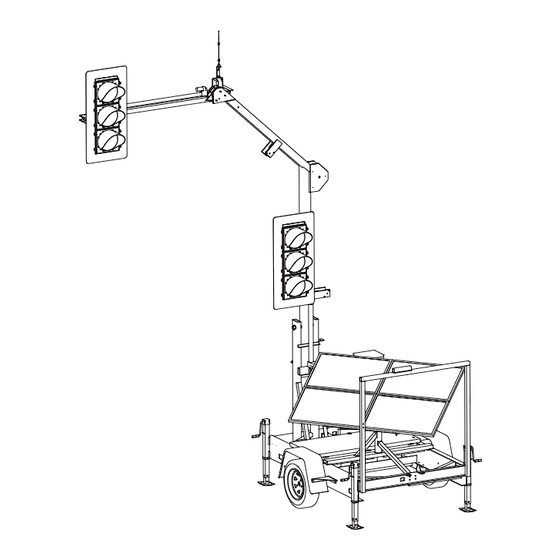
- Page 7 ECTION 1. LED Signal Lamps and Housing • 12” diameter, LED lamp module with high-fl ux lensing and complies with ITE standards. • ITE certifi ed polycarbonate housing with an aluminum backboard. • Standard ball cap visors extend over each LED lamp by 10” (tunnel visors available). •...
- Page 8 ECTION • High gain omni-directional antenna (standard on every trailer). 4. Diagonal Mast Arm Support • the square, aluminum arm that connects the Horizontal Mast Arm to the Main Light Post. 5. Main Light Post • the round, aluminum post. When deployed, this post sits in the vertical position. 6.
- Page 9 ECTION 1. Controller – controls all functions of the PTL 2.4x. 2. Transfer Flasher Relay (TFR) – transfers control of the local signal indications in the event of a fault. 3. Wiring Conduit – protected channel through which wires are routed. 4.
- Page 10 ECTION ground, and that the trailer is level. 3. Disconnect PTL 2.4x tongue from the hitch of the towing vehicle. CAUTION 4. Remove the wheels for added security using a standard tire iron (optional). ALWAYS check for overhead power lines or u lity lines in the immediate area to avoid contact with the 5.
- Page 11 ECTION 6. Unlock the mast arm from the mast arm support and move it into position. a. Remove cotter pin from locking pin. b. Remove locking pin. c. Swing mast arm support towards the rear of the signal. c. Swing the mast arm towards the front of the machine.
- Page 12 ECTION a. Ensure the lock bar is open. b. Open the control cabinet. c. On the switch plate, use the LIGHT POST toggle switch to raise the light post. b. Tilt the solar panels to a 45° angle. d. Once the signal has been raised and is between the vertical supports, place the lock bar in place and lock with the pad lock provided.
- Page 13 ECTION 2. Lower the signal post. a. Unlock the pad lock and open the signal post lock bar. CAUTION ALWAYS check for overhead power lines or u lity lines in the immediate area to avoid contact with the light post and horizontal mast arm. CAUTION b.
- Page 14 ECTION b. Remove the locking pin. c. Push up on the mast arm support to place in between the supports and line up holes for locking pin. d. Put locking pin into holes. c. Swing mast arm toward the mast arm support.
- Page 15 ECTION d. Secure the locking pins with cotter pins. e. Plug in the trailer running light plug. 6. Raise screw jacks. a. Connect trailer to truck using the ball hitch coupler. b. Crank the screw jack until the base is off the ground.
- Page 16 ECTION The main light post and horizontal mast arm will need to be manually lowered in the event of: • Dead batteries • Actuator failure (inoperable) Note: Use traffi c control persons to control traffi c fl ow when lowering the main light post and retracting the horizontal mast arm.
- Page 17 ECTION Always check for overhead power lines or utility lines in the immediate area to avoid contact with the trailer and light post. Also make sure there is enough clearance beside the machine when the mast arm is swung open. CAUTION •...
- Page 18 ECTION The PTL 2.4x signal heads have the ability to turn 180° and face the opposite direction. This allows the unit to be placed on the opposite side of the road in the event that there is little to no shoulder. High-Low 1.
- Page 19 ECTION Gen 3 Controller 1. Soft Buttons – these 10 buttons have no specifi c assigned values. They will have a different value on each screen. 2. BACK Button – returns to the previous menu screen. 3. L.E.D. Status Lights: - indicates whether there is a ALERT fault or error message.
- Page 20 ECTION The systems tray will display pertinent information that is always visible. DEFAULT ALL RED FEB/01/17 09:53AM PRESS START TO RESUME PROGRAM: MODEL V## BATTERY: 24.0 VOLTS HOME UNIT: PRIMARY RADIO CHANNEL: 03 RADIO SIGNAL: 1. System Feedback – this will display any instructions, faults or error messages that occur. 2.
- Page 21 ECTION Once unlocked, the only way to lock the software again is to go back to the OPTIONS menu and select the corresponding soft button. DEFAULT FLASH RED FEB/01/17 09:53AM PRESS START TO RESUME PROGRAM: MODEL V01 BATTERY: 24.0 VOLTS HOME >...
- Page 22 ECTION DEFAULT FLASH RED DEFAULT FLASH RED FEB/01/17 09:53AM FEB/01/17 09:53AM PRESS START TO RESUME PRESS START TO RESUME PROGRAM: MODEL V## PROGRAM: MODEL V## BATTERY: 24.0 VOLTS HOME BATTERY: 24.0 VOLTS HOME UNIT: PRIMARY RADIO CHANNEL: 03 RADIO SIGNAL: UNIT: SECONDARY 1 RADIO CHANNEL: 03 RADIO SIGNAL:...
- Page 23 ECTION approaching vehicle detected will send a Locking – Enables the controller to remember command to the controller and that phase or hold a vehicle call (even after the calling will become active. If an approaching vehicle leaves the detection area) until satisfi ed vehicle is detected by another traffi...
- Page 24 ECTION Default Behavior – allows the user to set the signal default mode that will be displayed in DEFAULT FLASH RED FEB/01/17 09:53AM the event of a fault (displayed across network). PRESS START TO RESUME PROGRAM: MODEL V## Note: Each Secondary unit can be modifi ed BATTERY: 24.0 VOLTS HOME >...
-
Page 25: Auxiliary Equipment
ECTION Communication Settings – used for radio communication setup. DEFAULT FLASH RED FEB/01/17 09:53AM PRESS START TO RESUME PROGRAM: MODEL V## BATTERY: 24.0 VOLTS HOME > OPTIONS PG 3 DEFAULT FLASH RED FEB/01/17 09:53AM UNIT: PRIMARY RADIO CHANNEL: 03 RADIO SIGNAL: PRESS START TO RESUME PROGRAM: MODEL V## PREV... -
Page 26: Language Settings
ECTION interface on models PTL 2.4x and PTL 2.4LD. Contact North America Traffi c before altering this setting. Both FLASH YELLOW and FLASH RED function as DEFAULT FLASH RED FEB/01/17 09:53AM a regular program. To stop, user must push ALL PRESS START TO RESUME PROGRAM: MODEL V## STOP. - Page 27 ECTION ◦ Select AJUSTES DE IDIOMA (LANGUAGE SETTINGS). ◦ Select SELECCIONE EL IDIOMA (SELECT LANGUAGE). ◦ Use the DOWN arrow button to toggle the selection to ENGLISH; press the ENTER button. ◦ Power off the system and wait 15 seconds for the controller to fully power down (LED lights on faceplate go dark).
-
Page 28: Primary Setup
ECTION When setting up a work zone, one unit must be set as the Primary Unit, and all others set as Secondary units. All Secondary Units should be powered on fi rst. Edit the WORK ZONE SETUP and OPTIONS menu settings as shown below on the Primary and Secondary controllers;... -
Page 29: Control Mode
ECTION iii. Select MODE; Rest Red, Rest Green, Last Served, Nil (Fixed Time). Edit LOCKING; YELLOW LOCK or NON-LOCK. Enter PASSAGE TIME. Enter FORCE MIN RECALL time (if applicable). f. Ensure unit is set to desired CONTROL MODE (AUTO or MANUAL). See OPTIONS PAGE 1>CONTROL MODE. - Page 30 ECTION...
- Page 31 ECTION...
- Page 32 ECTION...
- Page 33 ECTION...
- Page 34 ECTION...
- Page 35 ECTION Advanced Mode is a useful tool that enables the operator full control over the traffi c fl ow and traffi c control trailers. To set a unit into ADVANCED MODE, from the home screen select OPTIONS. Scroll down the options pages until LEVEL OF OPERATION is in view.
- Page 36 ECTION 9. Phase Settings Chart - the area used to input timing parameters and settings for all phases. BACK ENTER • The hard arrow buttons will move the selection box around the screen. • Pressing ENTER will open the highlighted parameter for editing. •...
- Page 37 ECTION inputs (ex. Microwave Traffi c Sensor) to each machine as required. First select a plan to edit. Use the side soft button Note: Sensor 32 pairs to select VIEW/EDIT PLAN NUMBER. Use UP and with Head A, Sensor 33 DOWN arrow buttons to cycle through editable pairs with Head B.
- Page 38 ECTION vehicle movement. Assign units to the parallel a phase will remain green. Used only when movement in the same way as the main vehicle actuation is enabled. movement. • MAX GREEN - The maximum time in seconds a The Editing Phases chart below indicates the phase will remain GREEN until it returns to RED.
-
Page 39: Day Of The Week
ECTION sensor assigned to another phase. HOME > WZ SETUP > PHASE SETTINGS > EDIT PHASE 1 FEB/01/17 09:53AM • LOCKING – Enables the controller to remember EDITING - PHASE 1 or hold a vehicle call (even after the calling vehicle leaves the detection area) until satisfi... -
Page 40: Time Of Day
ECTION Press BACK or ENTER to save and close. Notice a HOME > WZ SETUP > PHASE SETTINGS FEB/01/17 09:53AM tab appears with the selected start time. Create additional start times as required. Note that two start times are required to have any affect. PRI-A PRI-A SELECT DAYS TO OPERATE PLAN:... - Page 41 ECTION through the plans. Locate the required plan. To Within the PHASE STATUS SCREEN the following edit or change a plan, refer to sections 8.3 and information can be viewed: 8.4. • PLAN - The plan being run. On the opposite side of the screen, cycle through •...
- Page 42 ECTION 11. Create TIME OF DAY tabs for 6:00AM, 9:00AM, 4:20PM, and 7:10PM in the weekday tab. 12. Input the required timing and parameters for all phases, for each time of day change that is assigned to each day (or grouping of days). Note: For actuated phases 3 and 7: - input both MIN and MAX GREEN times - input PASSAGE time...
- Page 43 ECTION The Gen 3 CU has the capability of interfacing and operating with North America Traffi c’s previous generations of traffi c signal controllers, known as Gen 1 and Gen 2. Gen 1 - Portable Traffic Signal Controller Gen 2 Controller STOP FLASH MENU...
- Page 44 ECTION As with all generations of CU, all the secondary units to be used in the network should be: • Powered before the primary unit • Proper unit ID assigned (refer to S 9.2 O 1 for designation of proper unit ECTION PERATING ID’s based on the generation of CU)
- Page 45 ECTION Gen 3 models PTL 2.4x, PTL 2.4LD and TTS 3.7 will operate with Gen 1 units using program versions 1-9, 1-10 or 2-10. It is important to note a single GEN 3 unit can be operated in compatibility mode with Gen1.
- Page 46 ECTION The Gen 2 and Gen 3 share similar software structures when it comes to unit ID’s and work zone layouts. Refer to the chart below for further detail when setting up the Gen 2 secondary units. Note: The numbered boxes indicate the assigned phase (i.e. 1 = phase 1, 2 = phase 2) GEN 3 SETUP GEN 2 Secondary Unit ID's SITE LAYOUT...
-
Page 47: Troubleshooting
ECTION 10.1 The FAULT LOGS records both systems faults, as well as operational data. 10,000 events are held in memory for viewing on-screen or by means of export to a spread sheet fi le format. Note: to see full list of system fault messages, see S 15 T ECTION ROUBLESHOOTING... -
Page 48: Diagnostic Screen
ECTION 10.2 Using the directional buttons from OPTIONS HELP the HOME screen will allow you to view the PHASE STATUS and DIAGNOSTIC screens for each unit in the network. Press ENTER to view the selected tab. SEC1 Diagnostic Screen: Status of Lamps – graphic displays the active lamp. DEFAULT FLASH RED FEB/01/17 09:53AM PRESS START TO RESUME... - Page 49 ECTION 11.1 The radio remote does not have an on/off switch. Pressing and holding any button will turn the radio on. The radio will automatically turn off after releasing a button. The radio frequency range is 910 MHz - 917 MHz (spread spectrum, frequency hopping) and operates at less than 1 watt of power.
-
Page 50: Setting The Radio Channel
ECTION Setting the Radio Channel: Note: Setting the radio channel of the remote can be done at either the Primary or Secondary unit. 1. From the OPTIONS menu, select SYNC RADIO REMOTE. 2. Pressing and holding the black and red buttons at the same time after selecting SYNC RADIO REMOTE on the controller will confi... - Page 51 ECTION 11.2 The microwave traffi c sensor will identify a vehicle moving in its detection area and then trigger the operation of the traffi c controller. The device will provide accurate and consistent vehicle detection that is not affected by temperature, humidity, color, or background variations. The MTS can be set to trigger the controller when the traffi...
- Page 52 ECTION The RMS systems allow for asset location tracking and geofencing via a secured website (a geofence is a virtual barrier which is set in the GPS software). The battery bank voltage can also be remotely monitored. Cellular Satellite - Communicates from the portable - Communicates from the PTS to traffi...
- Page 53 ECTION 11.6 The directional antenna is intended for use in long distance work zones, and/or work zones varying in elevation (i.e. Pilot Car work zones). This antenna has an operational range up to 7 miles (11.3 km) with line of site. The directional antenna can easily replace the standard omni-directional whip antenna, and vice versa.
- Page 54 ECTION 12.1 Best Practices: • Operate with strong radio signal strength. At least 50% strength consistently (see Systems Tray). • Operate within 1/2 mile (0.8 km) apart including line of site (if using the standard omni-directional antenna). Common Interference: • Anything that interrupts line of sight between the units. i.e. tractor trailers, bridges, heavy equipment, elevation changes.
- Page 55 ECTION 13.1 The PTL 2.4x has a solar array consisting of four (4), 100 Watt solar panels, for a total collection of 400 Watts. The solar array is regulated by a 20 amp regulator. The solar array provides only supplemental charge to the battery bank and does not allow for infi...
- Page 56 ECTION Factors that affect battery autonomy are: Temperature Extreme temperatures (both high and low) can dramatically affect battery autonomy and charging. High Heat increases water usage and can result in overcharging and depletion of water, leading to damage. Batteries naturally discharge at temperatures above 49° Celsius (120° Fahrenheit). Batteries require less time to charge in high temperatures, which can result in rapid over-charging and damage to the batteries.
-
Page 57: Connection And Operation
ECTION 13.3 The battery charger is used to recharge the batteries by means of connection to a 120 VAC power source (wall outlet or generator). The PTL 2.4x has a 40 Amp charger with a maximum power output of 960 Watts (at 24 VDC). - Page 58 ECTION Please refer to website for latest maintenance forms. www.northamericatraffi c.com 14.1 Performing routine maintenance on your Portable Traffi c Signal is critical to ensuring safety while in tow, as well as the longevity of the trailer and its components. The items below are critical components that should be inspected on a monthly basis.
- Page 59 ECTION Inspection of Trailer Components: a. Check Tongue Hitch Coupler: Routinely check that the tongue hitch coupler is torqued to 45 ft/lbs. b. Check Hitch Coupler Components: Check the hitch coupler components to ensure the latch has full range of motion. Ensure the coupler locks on the ball without movement or play.
- Page 60 ECTION Message Descrip on Cause Solu on CHECK SETTINGS THEN PRESS Primary unit is ready to op- Machine(s) running properly Press “Start” bu on on START erate Primary when ready to start program CYCLE PAUSED While running automa c cycle User has paused the cycle Press the green bu on on (all red) with the hand held HHR when ready to start...
- Page 61 ECTION Message Descrip on Cause Solu on REPAIR COMMUNICATION Communica on failure is seen Primary and Secondary “x” are Move machines closer or use by the primary unit too far apart hardwired connec on Primary and Secondary “x” do Move machines to achieve not have line of sight line of sight or use hardwired connec on...
- Page 62 ECTION Message Descrip on Cause Solu on ALL STOP System is in “all red”, All stop has been triggered by Press “START” bu on on Secondary unit radio remote or “ALL STOP” Primary, when ready to start bu on on the Primary or Sec- program ondary controller Press “RESUME PROGRAM”...
- Page 63 ECTION Message Descrip on Cause Solu on MALFUNCTION RESPONSE MMU detected that no lamps All LED lamps not connected Connect LED lamps NO LAMPS (DARK) REPAIR were displayed MACHINE Faulty controller Replace controller MALFUNCTION RESPONSE MMU detected a ming fault LED lamp(s) not connected Connect LED lamp(s) CHECK LAMP WIRING...
- Page 64 ECTION Part Name Part Number Gen 3 Controller 500-0676 Gen 3 TFR 500-0677 J1 Harness 400-0212 J2 Harness 400-0213 J3 Harness 400-0214 6 Position Fuse Block 500-0355 40A 24V Battery Charger 500-0730 6V Battery 500-0149 24V Solar Panel (Dasol) 500-0782 20A Regulator 500-0674 T-Handle Latch...
Need help?
Do you have a question about the PTL 2.4 Series and is the answer not in the manual?
Questions and answers
Hard wired PTL 2.4X goes to cycle pause after starting
The North America Traffic PTL 2.4 Series hard wired PTL 2.4X may go to cycle pause after starting because the UI disables the operation sequence of the light slightly. This behavior is related to the controller interface on models PTL 2.4x and PTL 2.4LD and may be due to specific settings or timing configurations.
This answer is automatically generated
What does UI mean…