
Summary of Contents for MEVOCO RP800
- Page 1 Self & Dual Powered Overcurrent & Earth Fault Protection Relay User Manual Mevoco nv, Industrielaan 33A, 9800 Deinze, Belgium +32 (0)9/380 30 49 • info@mevoco.be • www.mevoco.be DW652322...
- Page 2 The information provided applies to the RP800 as a standard model. Mevoco nv cannot therefore be held liable for any damage resulting from specifications of the RP800 that deviate from the standard model.
-
Page 3: Table Of Contents
TABLE OF CONTENTS RECEPTION, HANDLING & INSTALLATION NPACKING ECEPTION OF RELAYS ANDLING ELECTRONIC RELAY NSTALLATION COMMISSIONING AND SERVICE TORAGE ECYCLING DIMENSIONS AND CONNECTION DIAGRAMS RONT VIEW ASE DIMENSIONS ONNECTION DIAGRAM 2.3.1 TANDARD CURRENT TRANSFORMERS 2.3.2 TANDARD CURRENT TRANSFORMERS ERMINALS DESCRIPTION NTRODUCTION ELAY DESCRIPTION UNCTIONAL... - Page 4 OUNTERS EADBAND TATES AND EVENTS (RTC) ATE AND IME BY LOCK DIAGNOSIS ISTURBANCE AULT ECORDING ONFIGURABLE NPUTS 4.10 IGITAL UTPUTS 4.11 ROGRAMMABLE OGIC ONTROL 4.11.1 UTPUTS 4.11.2 4.12 OMMANDS 4.13 4.14 OWER SUPPLY 4.14.1 OWERED RELAY WITH STANDARD CURRENT TRANSFORMERS 4.14.2 24-230 V , 50/60 H...
- Page 5 6.7.14 OUNTERS 6.7.15 OMMANDS 6.7.16 ROFILING 6.7.17 AULT EPORTS 6.7.18 UTPUTS ONFIGURATION COMMISSIONING HECKLIST FOR OMMISSIONING LECTROSTATIC DISCHARGE ISUAL NSPECTION ARTHING URRENT TRANSFORMERS UXILIARY POWER RONT COMMUNICATIONS PORT OMMISSIONING APPENDIX DENTIFICATION HECKS EST MENU EGISTER OF COMMISSIONING SETTINGS NPUTS UTPUTS OMMENTS...
-
Page 6: Reception, Handling & Installation
It is necessary to inspect the relay at the time it is delivered to ensure that the relays have not been damaged during transport. If any defect is found, the transport company and Mevoco should be informed immediately. If the relays are not for immediate use, they should be returned to their original packaging. -
Page 7: Installation, Commissioning And Service
1.4 Installation, commissioning and service The personnel in charge of installing, commissioning and maintaining this relay must be qualified and must be aware of the procedures for handling it. The product documentation should be read before installing, commissioning or carrying out maintenance work on the relay. -
Page 8: Dimensions And Connection Diagrams
2 DIMENSIONS AND CONNECTION DIAGRAMS 2.1 Front view 2.2 Case dimensions The dimensions are in mm: Option 1: Rear power terminals for 2.5 mm2 cable: DW652322... - Page 9 Option 2: Rear power supply terminals with ring terminals (cable 4 mm2 – model RP800): Cut-out pattern...
-
Page 10: Connection Diagram
2.3 Connection diagram 2.3.1 Standard current transformers 2.3.2 Standard current transformers Note! trigger: 6 - 24 Vdc & <= 0.135 W.s... -
Page 11: Terminals
2.4 Terminals Phase A current input for measurement and self-power Phase A current output for measurement and self-power Phase B current input for measurement and self-power Fase B stroomuitgang voor meting en eigen voeding. Phase C current input for measurement and self-power Phase C current output for measurement and self- power Neutral current input for measurement Neutral current output for measurement Auxiliary power supply + Auxiliary power supply - Common of the Inputs Input 1 Input 2 Input 3 Trip output low energy trip coil+ Trip output low energy trip coil - Digital 1 common output B10 Digital output 1 NC B11 Digitale output 1 NO B12 Digital output 2 common output B13 Digital output 2 NC B14 Digital output 2 NO B15 Digital output 3 commune B16 Digital output 3 NC B17 Digital output 3 NO B18-B19 RS485 Remote communication Use only copper conductors with a minimum temperature of 75ºC. - Page 12 There are 2 options for the current rear terminals: Option 1: Rear terminals for 24 AWG - 12 AWG cable: 0.25 - 2.5 mm2 with a torque of 0.5 Nm-0.6 Nm : Option 2: Rear power supply terminals with ring clamps (12 AWG - 22 AWG: 4 - 0.3 mm2 cable with torque of 0.79 Nm - Model SIABxxxxx7xx) : The other terminals (inputs, outputs, communication and auxiliary power supply) are designed for 24 AWG - 12 AWG cable: 0.25 - 2.5 mm2 with a tightening torque of 0.5...
-
Page 13: Description
(batteries). As a result, it is especially useful in any centers were auxiliary power is not available or cannot be guaranteed. The RP800 relay is housed in a metal box with galvanic isolation on all its measurement inputs and outputs (except for communications ports and battery power supply, as these are sporadic connections). - Page 14 There are four LED indicators on the front of the RP800 relay indicating the relay status and in case of fault trip the type of fault: LEDS DEFAULT CONFIGURATION LED 1 Ready LED 2 Neutral/Earth fault trip LED 3 Overcurrent trip LED 4 Thermal trip Besides, the relay is provided with 3 signaling outputs that are also configurable by the user.
- Page 15 Function Description RP-800 Protection 50_1 Phase instantaneous overcurrent protection function 50G_1 Ground nstantaneous overcurrent protection function 50/51 Phase inverse time overcurrent protection function 50/51G Ground nstantaneous overcurrent protection function 49T External trip SHB Second harmonic Blocking Thermal image PGC Programmable Logic Control Circuit Breaker monitoring State and control of the circuit breaker Number of openings counter Accumulated amperes counter: Maximum openings in a time window Measurements Phase and neutral RMS measurement with ±2% over ±20% over the nominal current and ±4% of ±5 mA in the rest of the range. Inputs and Outputs Via configureerbare External trip input (without power supply) ingangen Configurable inputs (without power supply) Trip output for STRIKER (135 mJ) Configurable signaling out (10A @ 30VDC-250) 3 (NO-NC) Communication and IHM Front port: micro USB (Modbus RTU) Rear port: RS485 (Modbus RTU of DNP3.0 Serial) SICom- Program HMI: LCD, 20x2 and 6 keys + 1 reset button + 1 Battery key LED -indicators Power supply Self-powering with standard CT’s:...
-
Page 16: Functional Diagram
3.3 Functional Diagram... -
Page 17: Function Shb. Second Harmonic Blocking
3.4 Function SHB. Second Harmonic Blocking The second harmonic blocking is used to avoid an undesirable behavior due to inrush current when energizing a machine like a transformer or a generator. Group Description Minimum Maximum Step Unit Default SHB Second harmonic blocking Function Enable Yes/No Current tap... -
Page 18: Function 51. Inverse Time Phase Overcurrent
3.6 Function 51. Inverse time phase overcurrent This protection function can be set by using five parameters: Function Description Minimum Maximum Step Unit Inverse time phase overcurrent Function Ja/Nee/SHB Enbale Curve type (1*) Time Dial 0,01 1,5 0,01 (TMS) Current Tap 0,2 7,00 0,01 xln Time Delay 0,02 0,01 (1*) IEC Inverse, IEC Very inverse, IEC Extremely inverse, IEC Long time inverse,... -
Page 19: Function 51G. Inverse Time Neutral Overcurrent
activates (trips) and does not reset itself until the value of the phase drops below the point of current pick-up. When the Function Enable is set to “YES”; the accuracy of the Time Delay is equal to the pre-set time ±30 ms or ±0.5% (whichever is greater). -
Page 20: Thermal Image Measurement Evolution Graphic
time depends on the thermal constants adjusted, the current flowing and the prior thermal state of the machine. The thermal image is calculated based on the following equation: θ = 100 x (I/It)2 x (1 - e-t/ζ) + θ'0 x e-t/ζ Where : I, maximum R.M.S.-current of three phases adjusted tap current... - Page 21 Supposing that thermal image protection has an adjusted tap of 1,1 times the nominal current and an alarm level of 75%: • Zone 1: The machine is de-energized for a long time. Thermal image is 0%. • Zone 2: The machine is supplied with the nominal current. Thermal image evolutions so as to get the value of the thermal balance corresponding to one time the nominal current Th = (I/It) 2 •...
-
Page 22: Thermal Image With Memory
3.9.2 Thermal image with memory Thermal image is stored in non-volatile RAM memory periodically. By this way, though the relay loses the power supply, it will keep the thermal state of the machine. 3.9.3 Thermal image measurement display. Reset. Thermal image measurement can be displayed on Measurement menu. 3.9.4 Thermal protection curves This is the thermal curve for ζ... -
Page 23: Function 52. Circuit Breaker Monitoring
3.10 Function 52. Circuit Breaker monitoring This function allows the status of the circuit breaker to be monitored and preventive maintenance to be performed, for which the following parameters need to be configured: Group Description Minimum Maximum Step Unit Circuit breaker monitoring Maximum number of 10,00 openings... - Page 24 time set in “Time of maximum repeated openings” The way that the circuit breaker is monitored becomes more or less complex depending on whether it is fitted with no breaker contacts, one breaker contact (52a or 52b) or both (52a and 52b). If no breaker contacts are used, the monitoring of the circuit breaker is made through the current measurement.
- Page 25 The circuit breaker performance is shown in the following finite state machine:...
-
Page 26: Circuit Breaker Opening And Closing Commands
3.11 Circuit Breaker opening and closing commands The circuit breaker opening and closing commands are implemented. These commands can be executed from the HMI commands menu or using the HMI’s specific keypad or from local or remote communications. In order that the command related to the key can run, the menu must be in standby mode. -
Page 27: Function 49T. External Trip
This alarm resets itself, when the corresponding time is exceeded with less trips than those indicated. 3.15 Function 49T. External trip The relay has 3 configurable inputs and any of them can be configured as external trip input (by default input 1 is configured as external trip input). All three inputs are normally connected to a bimetallic contact fitted to the power transformer. - Page 28 • Extremely Inverse Curve • Long time inverse There is a general mathematical equation that defines the time in seconds as a function of the current: ´ ´ adjusted Parameters Long Time Inverse 120 Ext. Inverse Very Inverse 13,5 Inverse 0,14 0,02 The curve can mode from its axis using the D time selection device, which the user can adjust.
-
Page 33: Ieee Curves
3.18 IEEE curves The IEEE-curves follow the following mathematical equation: é ù æ ö ´ ç ÷ ê ú è ø ë û adjusted where: And we have the following curves: ● Inverse Curve ● Very Inverse Curve ● Extremely Inverse Curve Which relate to the parameters figuring in the following Setting Group: Parameters Ext. Inverse... -
Page 37: Monitoring And Control
4 MONITORING AND CONTROL 4.1 Measurements Three-phase currents (I-A, I-B and I-C), neutral current (I-N), negative sequence current (I-2), second harmonic of each phase (IA-2H, IB-2H and IC-2H), maximum current (Imax) and thermal image (TI) are given as fundamental values (DFT). A sampling, of 16 samples/cycle, is performed. -
Page 38: Counters
4.3 Counters The following counters are provided: 1 Number of openings of the circuit breaker 2 Accumulated amperes (I2t) during the openings of the circuit breaker 4.4 Deadband The Deadband is a DNP3.0 setting. Once the deadband is set (in % of In), in case that the current exceeds the setting above or below, the relay will show the value of the current measurement. - Page 39 The following list shows all the states of the relay and their associated events: Register description State Event Caues Associated measurement General states Trip Trip Activation/Deactivation Maximum phase current External trip External trip Activation/Deactivation No Trip Power No Trip Power Activation/Deactivation 50 Hz Rip Block enable Trip Block enable Activation/Deactivation Measure error Measure error Activation/Deactivation 1: Vaux-power Ready Ready Activation/Deactivation 2: Self-powering...
- Page 40 Activation Phase B current 50 Phase B trip 50 Phase B trip Activation Phase C current 50 Phase C trip 50 Phase C trip 50 trip 50 trip Activation/Deactivation Maximum current Definite time neutral overcurrent 50G pick-up 50G pick-up Activation/Deactivation Neutral current 50G_1 50G trip 50G trip Activation Neutral current Inverse time phase overcurrent 50/51 Phase A pick- 50/51 Phase A pick- Activation/Deactivation Phase A current up 50/51 Phase B pick- 50/51 Phase B pick- Activation/Deactivation Phase B current up 50/51 Phase C pick- 50/51 Phase C pick- Activation/Deactivation Phase C current up up 50/51 50/51 pick-up 50/51 pick-up Activation/Deactivation...
- Page 41 Phase B Block Phase B Block Activation/Deactivation Phase B current Phase C Block Phase C Block Activation/Deactivation Phase C current Phase Block Phase Block Activation/Deactivation Maximum current Cold Load pickup (*) CLP Disable 52 Close 52 Open CLP 52 definitive Open Close Cold Load Open Cold Load Cold Load pickup Cold load pickup Activation/Deactivation Phase current Breaker Failure Supervision (*) 50BF pick-up 50BF pick-up Activation/Deactivation Phase current 50BF 50BF trip 50BF trip Activation/Deactivation Phase current Inputs Input 1 Input 1 Activation/Deactivation Input 2 Input 2 Activation/Deactivation Input 3 Input 3...
-
Page 42: Date And Time By Real Time Clock (Rtc)
A brief description of the general states is given below: • Trip: The relay has tripped. • External trip: A trip has been caused by the activation of the excess temperature input (external trip). • 50 Hz: If activated, the relay works at 50 Hz, if deactivated it works at 60Hz. •... - Page 43 2 situations appear on the main screen (EEPROM ERROR or EVENTS ERROR), the relay should be replaced, and it will be necessary to contact Mevoco. On the other hand, “Default settings” means that the relay is operating...
-
Page 44: Disturbance Fault Recording
4.8 Disturbance Fault Recording Disturbance fault recording includes the disturbance records in COMTRADE format and the data of each COMTRADE (fault reports). The relay can store, in FRAM memory, up to 20 fault reports with 16 events in each. From the standby mode screen, press “OK” key to access the first line of menus. - Page 45 ************************************************ ****************************** HDR COMTRADE The following information is included in each COMTRADE file: Number Analog channels Phase A current Phase B current Phase C current Neutral current This current is already in primary amperes. As well as the analogue magnitudes, the relay saves 32 digital records, with the same precision as 16 cycle samples.
- Page 46 It is possible to visualize the COMTRADE file using SICom software: Using SICom software, it is possible to save the COMTRADE file.
-
Page 47: Configurable Inputs
4.9 Configurable Inputs The SIA-B is provided with 3 digital inputs that can be configured by the user from the HMI or by using the SICom program. The default input configuration is shown below: Logic In 1 In 2 In 3 52 a 52 b External trip... -
Page 48: Outputs
4.11.1 Outputs All the outputs (Physical outputs) are the result of a PROGRAMMABLE LOGIC CONTROL which can be configured from HMI or from SICom software. For each output, there is a LOGICAL GATE. It can perform a logical operation up to 4 binary states to obtain other binary result. -
Page 49: Leds
By default, the configuration is: OUTPUT LOGICAL GATE BINARY STATE Output 1 NOR4 Ready Phase trip Output 2 AND4 General trip PHYSICAL OUTPUT Output 3 Ground trip AND4 General trip Trip Output OR4_PULSES General trip 52 a Not configured 52 b Not configured External trip Input 1... - Page 50 So, the LEDs will light as follows: SIGNAL ASSOCIATED TO THE LED KEEPS ITSELF ACTIVATED The signal that origins the activation of the LED remains activated (the LED and the associated signal are activated at the same time): In this case the LED will blink at a fixed frequency.
- Page 51 The configured signal will make a pulse of the adjusted milliseconds once the input signal is activated. Input Output The configured signal Waits the adjusted milliseconds to activate itself. Input Output The configured signal will be activated till it is externally reset (command, reset key, Communications …), though the input signal drops off.
-
Page 52: Commands
4.12 Commands By HMI or by communications, depending on model is possible to: • Open Breaker • Close Breaker • Reset Thermal Image When Open Breaker command is performed, the trip output is activated (originating the corresponding event) and the message “trip general” will be displayed on main screen 4.13 Test Menu The SIA-B relay has a test menu that can be used to check the operation of the... -
Page 53: Power Supply
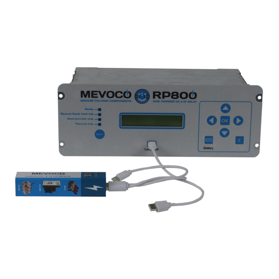
4.14 Power supply The SIA-B relay is designed to be self-powered using the cell current. Besides, depending on model it is possible to select apart from self-powered an auxiliary supply (24-230 Vdc/Vac +10%/-20% (Dual)). It can also be supplied from a USB cable which goes directly to the PC. The USB is plugged into the front communications port. -
Page 54: Battery Power : 5 V, With Akitcom Adaptor
4.14.4 Battery power: 5 V, with a KITCOM adaptor The external 5 V battery is connected to the relay through an adapter that is plugged into the front communications port (KITCOM). It is useful for cases like commissioning operations, discharges and repairs to the transformation center, as these are situations when there is no auxiliary voltage or current in the line and they normally cause more events, grounding, forgotten tools, bad terminations, etc. - Page 55 events and the fault reports is possible and this action allows the user to know all the information regarding the fault situation. The working of the relay is independent from the internal battery. This battery is just an accessory that allows the user to set the relay and to analyze the information recorded in fault reports and events menus, but it does not take part on the main working of the relay.
- Page 56 Unscrew the 2 screws to remove the cover from the battery compartment. Remove the battery and replace it respecting polarity (+ facing up) : Battery characteristics: AA 3.6V lithium battery Model LS14500 from SAFT Do not use rechargeable batteries or other types of battery Put on the battery cover and tighten the 2 screws.
- Page 57 Put the relay into the RMU switchgear and tighten the 4 screws on the front to fix the relay.
-
Page 58: Switch On To Fault (Sotf) Characteristic
Warning HAZARD OF EXPLOSION ● Do not recharge the battery. ● Do not short circuit the battery. ● Do not crush the battery. ● Do not disassemble the battery. ● Do not heat the battery above 100ºC (212ºF). ● Do not throw the battery into fire or water. Failure to follow these instructions can result in death, serious injury, or relay damage. -
Page 59: Opening Mechanism: Striker
On the other hand, if a higher level that the required by the striker is selected, the activation of the striker is guaranteed, however, the fault trip time during start-up may be increased. MEVOCO encourages selecting the correct value of this critical setting and offers its expertise at any doubt. -
Page 60: Technical Specifications And Standards
5 TECHNICAL SPECIFICATIONS AND STANDARDS 5.1 Technical Specifications Function Enable: Yes/No/SHB Current Tap: 0,2 to 20 xln (not 0,01 xIn) Time Delay: 0,02 to 2 s (step 0,01 s) Activation level: 100%. 50_1 Deactivation level: 95%. Instantaneous deactivation Timing accuracy : Without SHB permitted: ±... - Page 61 Timing accuracy for defined time curve selection: Without SHB permitted: ± 30 ms or ± 0,5% (greater of both). With SHB permitted: ± 50 ms or ± 0,5% (greater of both). Function enable: Yes/No Current Tap: 5 to 50% (step 1%) Reset Time: 0.00 to 300.00 (step 0.01 s) Block Threshold: 0,07 to 20,00 xIn (step 0,01 xIn) Activation level: 100%.
-
Page 62: Thermal Resistance
Operating temperature : -40 to 70°C Environmental conditions Humidity: 95% Transformers Power supply and measurement standards CTs /1 Metallic box Panel Mounting Height x Width: 90 mm x 245 mm Mechanical features Depth: 139,4 mm Weight: 3 kg IP-54 panel mounted Thermal resistance ●... -
Page 63: Led Indicators
one side, and all the - terminals on the other must be connected together in order to make the connection. Resistors should be used at each end if very long cables are used. The best solution for avoiding reflection is to install resistors at both ends of the cable. The ohm value of these resistors must be equal to the cable impedance value. -
Page 64: Sicom Communications Program
settings parameters, measurements, state and events. The whole information is organized in a system of menus. A keypad is fitted to the relay front panel, which can be used to access the information shown on the LCD screen and to navigate through the menu system. This keyboard is provided with 6 keys that can be used to navigate through the different menus and to change the setting parameters. -
Page 65: Setting-Up The Session: Password And Access Levels
6.6 Setting-up the session: Password and access levels The relay is provided with different passwords associated to access levels allowing the user to carry out different actions depending on the selected password: Access level Read-only Function Change Function Function Function enable : enable to: settings enable to :... -
Page 66: Menus
6.7 MENUS 6.7.1 Standby mode screen The default screen shows the device model and the currents in phase A, phase B, phase C and Neutral. Press ‘OK’ to select a menu : measurements, states, settings and events. If the HMI is left in any state, it will return to the default screen after 5 minutes without any key being pressed. -
Page 67: Versions
6.7.4 Versions The relay versions menu can be accessed from the standby mode screen by pressing the key “▲”. This displays the software versions of the relay processors. Press the “C” key to return to the standby mode screen. 6.7.5 Communication parameters The Communications parameters can be viewed holding down the “▼”... -
Page 68: Testmenu
● In case there are fault reports recorded: The name of the fault reports indicates the function that has tripped and originated the fault report. 6.7.8 TestMenu The "Test menu" is accessed from the standby mode screen by sequentially pressing the "◄", "▼"... -
Page 69: Functions Menu
6.7.9 Functions Menu The SIA-B relay menu is split up into 8 main parts: ● Measurements. ● States. ● Settings. ● Events. ● Counters. ● Commands. ● LDP (load data profiling – current demand). ● Fault reports. - Page 70 Press the "OK" key to access the second level from the main screen. Use the ▲ and ▼ keys to move from one menu section to another in the second level. Use the "C" key to return to a higher level.
-
Page 71: Measurements Menu
6.7.10 Measurements Menu From the standby mode screen, press the "OK” key to access the First line of menus. Use the "▲" and "▼" keys to position the cursor over the “MEASUREMENTS” screen and press "OK". Use the "▲" and "▼" keys to position the cursor over the measurement and to see its value. -
Page 72: States Menu
6.7.11 States menu ↑ STATES SIAB110FD132AC ↓ 0.00 0.00 0.00 0.00 ↑ STATES Sta. GENERAL >Activated ↓ Trip: Sta. GENERAL not activated External Trip: ▲▼ not activated NO Trip power: ▲▼ not activated 50 Hz: ▲▼ <<ACTIVATED>> Triblock Enab.: ▲▼ not activated Error Measure: ▲▼... - Page 73 Error Eeprom: ▲▼ not activated Eeprom changed: ▲▼ not activated Error Event: ▲▼ not activated Pickup: ▲▼ not activated Phase A Pickup: ▲▼ not activated Phase B Pickup: ▲▼ not activated Phase C Pickup: ▲▼ not activated Ground Pickup: ▲▼ not activated Phase A Trip: ▲▼...
- Page 74 Phase Trip: ▲▼ not activated Aux. Power: ▲▼ not activated Self-Power: ▲▼ not activated USB Power: ▲▼ not activated Battery: ▲▼ not activated ↑ STATES Sta. 50-1 ▲▼ ↓ Phase A Pickup: Sta. 50-1 not activated Phase B Pickup: ▲▼ not activated Phase C Pickup: ▲▼...
- Page 75 ↑ STATES Sta. 51 ▲▼ ↓ Phase A Pickup: Sta. 51 not activated Phase B Pickup: ▲▼ not activated Phase C Pickup: ▲▼ not activated Phase Pickup: ▲▼ not activated Phase A Trip: ▲▼ not activated Phase B Trip: ▲▼ not activated Phase C Trip: ▲▼...
- Page 76 ↑ STATES Sta. 51G ▲▼ ↓ Ground Pickup: Sta. 51G not activated Ground Trip: ▲▼ not activated ↑ STATES Sta. SHB ▲▼ ↓ Phase A Block: Sta. SHB not activated Phase B Block: ▲▼ not activated Phase C Block: ▲▼ not activated Phase Block: ▲▼...
- Page 77 52 Open Error: ▲▼ not activated 52 Close: ▲▼ not activated 52 Close Time: ▲▼ not activated 52 Close Error: ▲▼ not activated Open Num.Alarm: ▲▼ not activated I2t Alarm: ▲▼ not activated Open/Time Alarm: ▲▼ not activated ↑ STATES Sta.
- Page 78 Output 3: ▲▼ not activated Trip Output: ▲▼ not activated ↑ Sta. LEDS STATES ▲▼ ↓ > Activated Led1: Sta. LEDS <<ACTIVATED>> Led2: ▲▼ not activated Led3: ▲▼ not activated Led4: ▲▼ not activated ↑ Sta. LOGIC STATES ▲▼ ↓ 52a: Sta.
- Page 79 Reset: not activated Logic Sig1: not activated Logic Sig2: ▲▼ not activated Logic Sig3: not activated Logic Sig4: not activated ↑ STATES Sta. LOCAL ▲▼ ↓ Local COM.: Sta. LOCAL not activated HMI Activity: ▲▼ <<ACTIVATED>> Open Breaker: ▲▼ not activated Close Breaker: ▲▼...
- Page 80 Remote communication depends on the selected setting in general settings: Internal communication: MODBUS RTU : ↑ Sta. MODBUS STATES ▲▼ ↓ Remote COM.: Sta. MODBUS not activated Open Breaker: ▲▼ not activated Close Breaker: ▲▼ not activated Reset TI: ▲▼ not activated External communication: DNP3.0 Serieel : ↑ STATES...
-
Page 81: Settings Menu
6.7.12 Settings Menu From the standby mode screen, press the “OK” key to access the first line of menus. Use the “▲” and “▼” keys to position the cursor over the “SETTINGS” screen and press “OK”. This takes you to the setting groups’ line. Use the “▲” and “▼” keys to position the cursor over a settings group, and press the “OK”... - Page 82 SETTINGS SIAB110FD132AC ↑ 0.00 0.00 ↓ 0.00 0.00 SETTINGS ↑ Select Group ↑ (Active ↓ ↓ Group) ↑ ▲ Select Group ▼ ↓ ↑SETTINGS Sett(2) 50-1 ↓ Function Sett(2) 50-1 Enable Function Set Password Enable -> 0 ◄▼ Set Password ▲►...
- Page 83 ▲ Current Tap ▼ 5.00 xIn ▲ Time Delay ▼ 0.2 s ↑SETTINGS ▲ Sett(2) 50-2 ▼ ↓ Function Sett(2) 50-2 Enable ▲ Current Tap ▼ 5.00 xIn ▲ Time Delay ▼ 0.2 s ↑ SETTINGS ▲ Sett(2) 51 ▼ ↓...
- Page 84 ▲ Time Delay ▼ 0.20 s ↑ SETTINGS ▲ Sett(2) 51G ▼ ↓ Function Sett(2) 51G Enable ▲ Curve type ▼ IEC E.I Time Dial ▲ (TMS) ▼ 1.25 ▲ Current Tap ▼ 0.20 xIn ▲ Time Delay ▼ 0.20 s ↑...
- Page 85 Max. ▲ Accumulated ▼ 1000 M(A2) ▲ Max. Open Time ▼ 0.10 s Max. Close ▲ Time ▼ 0.10 s Repetitive ▲ Open Num ▼ Repetitiv Open ▲ Time ▼ 9 min ↑ SETTINGS ▲ Sett(2) 50BF ▼ ↓ Function Sett(2) 50BF Enable ▲...
- Page 86 Language ▲▼ ENG. Active ▲▼ Settings G. Trip Vol. ▲▼ Level 17 Vdc CT Phase Ratio ▲▼ CT Neutral ▲▼ Ratio Local COM ▲▼ Address Remote Address ▲▼ Remote ▲▼ BaudRate 19200 Remote ▲▼ Protocol (**) (**) Depending on the selected remote communication: MODBUS: Remote ▲▼...
- Page 87 DNP3: Remote ▲ BaudRate ▼ 19200 Remote ▲ Protocol ▼ DNP3 DNP3 ▲ Master ▼ Address DNP3 ▲ Serial ▼ Setting 8-N-1 DNP3 Serial ▲ Password Setting ▼ -> 0 8-N-1 DNP3 IA ▲ Deadband ▼ 20 % Set Password ◄▼▲►...
-
Page 88: Events Menu
6.7.13 Events Menu From the standby mode screen, press the "OK" key to access the First line of menus. Use the "▲" and "▼" keys to position the cursor over the "EVENTS" screen and the number of events in the buffer will be displayed. Press "OK" and use the "▲" and "▼” keys to position the cursor over the events. -
Page 89: Counters Menu
The "┘" and "┐" shows the event has been caused by the activation or reset of the associated state. To delete the events buffer, position the cursor over the events menu and press 'RESET' key, until there is only one event shown. This one event is "Deleted events”. Each event contains the following information: ●... -
Page 90: Commands Menu
Openings ▲▼ Number -> 5 Accumulated Openings ▲ Amps Number ▼ 0 k(A2) 6.7.15 Commands Menu The First line of menus can be accessed from the standbymode screen by pressing the "OK” key. Use the "▲" and "▼" keys to move the cursor through the different screens until it is positioned over the "COMMANDS"... -
Page 91: Load Data Profiling
6.7.16 Load Data Profiling From the standby mode screen, press the "OK" key to access the first line of menus. Use the "▲" and "▼" keys to position the cursor over the "FAULT REPORT" screen. Press "OK" and use the "▲" and "▼" keys to position the cursor over the Fault Report. -
Page 92: Pgc And Outputs Configuration Menu
6.7.18 PGC and Outputs Configuration Menu To assign an instantaneous state to a physical output, browse through the STATE menu to find the desired instantaneous state. When the state appears, press ► to enter the output configuration menu. Use the "▲" and "▼" keys in this menu to find the desired physical output. - Page 93 Phase B Pickup>?0 ▲▼ Output 2 y/n? ◄ Phase B ↑Sta. 50-1 Pickup>+0 ↓ Output 2 y/n? Configuration Processing... Con ¼ Output 2 Phase B Pickup Phase B Pickup>t0 ◄ Output 2 y/n? Phase B Pickup>&0 ◄ Output 2 y/n? Phase B Pickup>§0 ◄ Output 2 y/n? Phase B Pickup>c0...
- Page 94 Phase B Pickup>Φ ◄ Output 2 y/n? Phase B Pickup>$.25 Output 2 y/n? Phase B Pickup>Q.25 Output 2 y/n? Phase B Pickup>q.25 Output 2 y/n? Phase B Pickup>R.25 Output 2 y/n? Phase B Pickup>r.25 Output 2 y/n? Phase B ▲ Pickup>?0 ▼...
- Page 95 Phase B ▲ Pickup>?0 ▼ SettingsG2 y/n? Phase B ▲ Pickup>?0 ▼ Reset y/n? Phase B ▲ Pickup>?0 ▼ Logic Sig1 y/n? Phase B ▲ Pickup>?0 ▼ Logic Sig2 y/n? Phase B ▲ Pickup>?0 ▼ Logic Sig3 y/n? Phase B ▲...
-
Page 96: Commissioning
7 COMMISSIONING 7.1 Checklist for Commissioning The commissioning sheets that are needed to register the commissioning process and the specific settings for each installed piece of relay are found in the Appendix. 7.2 Electrostatic discharge Before handling any of the relay electronic components, make sure that you have read the section of the user manual related to electrostatic discharges. -
Page 97: Appendix
● MEVOCO recommends the use of the KITCOM accessory with a battery in the front port. This additional energy source allows the relay to be monitored and the trip to function without the need for self-power in any breakdown situation. - Page 98 CT Ratio : Phase CT Ratio: ..................... Neutral CT Ratio : ..................... 50_1 !"" !""No !""SHB Function Enable Tap........x In Time Delay : ...... s 50G_1 !"" !""No !""SHB Function Enable Tap........x In Time Delay: ...... s 50/51 !""...
-
Page 99: Inputs
8.5 Inputs Input-1. Input-2. Input-3. 8.6 Outputs Output-1. Output-2. Output-3. Trip Output: 8.7 Leds Led -1. Led -2. Led -3. Led -4. Ready Neutral/Earth fault trip Overcurrent trip Thermal trip 8.8 Comments …………….....…………………………………………………………………………… …………….....…………………………………………………………………………… ……………....……………………………………………………………………………. …………….....…………………………………………………………………………… …………….....…………………………………………………………………………… …………….....…………………………………………………………………………… …………….....…………………………………………………………………………… …………….....…………………………………………………………………………… …………….....……………………………………………………………………………... - Page 100 33A, 9800 Deinze, Belgium Mevoco nv, Industrielaan +32 (0)9/380 30 49 • info@mevoco.be • www.mevoco.be DW652121 ©2021 Mevoco nv...
Need help?
Do you have a question about the RP800 and is the answer not in the manual?
Questions and answers