Table of Contents
Advertisement
Quick Links
Advertisement
Table of Contents

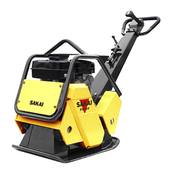
Summary of Contents for Sakai PF120
- Page 1 PF120/150 SHOP MANUAL 3498-64884-0...
- Page 3 Introduction This manual provides important information to familiarize you with safe operating and maintenance procedures for your SAKAI product. Even though you may be familiar with similar equipment you must read and understand this manual before operating or servicing this unit.
- Page 5 1-004 1-9. Stopping 1-004 1-10. Maintenance 1-004 1-11. Transporting the Machine 1-006 2. SPECIFICATIONS 1. SPECIFICATION DATA 2-001 1-1. PF120 2-001 1-2. PF150 2-002 2. FUEL AND LUBRICANT 2-003 2-1. Fuel 2-003 2-2. Recommended Lubricant 2-003 3. TIGHTENING TORQUE CHART 2-004 3.
- Page 6 1. GUIDE FOR USE OF PARTS CATALOGUE 4-001 2. FRAME (PF120) 4-002 3. HANDLE (PF120) 4-004 4. VIBRATOR (PF120) 4-006 5. NAME PLATE (PF120) 4-008 6. FRAME (PF150) 4-010 7. HANDLE (PF150) 4-012 8. VIBRATOR (PF150) 4-014 9. NAME PLATE (PF150) 4-016 5.
- Page 7 SAFETY...
-
Page 9: General Safety
SAFETY 1. GENERAL SAFETY 1-1. Understanding the Safety Symbols and Words The words DANGER, WARNING, and CAUTION are used with the safety-alert symbol. DANGER identifies the most serious hazard. When the symbols DANGER, WARNING and CAUTION are displayed, become alert. Your safety or those around you may be involved. NOTICE is used to provide important information that is not hazard related. - Page 10 SAFETY • The machine is designed specifi cally for the compaction of asphalt or soil road construction materials. Use of the machine for other purposes such as towing other equipment is considered contrary to the designated use. The manufacturer cannot be responsible or held liable for any damage resulting from such use.
-
Page 11: Pre-Start Inspection
SAFETY • Observe all safety instructions and warnings attached to the machine. • Make sure all safety instructions and warnings on the machine are complete and perfectly legible. • Stop the machine immediately in the event of any malfunction. Report any malfunction immediately to the supervisor or other person of authority. -
Page 12: Maintenance
SAFETY 1-8. Operating • Always make sure that there are no obstructions or persons in your line of travel before starting the compactor in motion. • Use caution and be very observant when operating in close quarters and congested areas. •... - Page 13 Always clean up any spilled fuel. • Ensure safe operation, optimum performance of the machine and its warranty by using only genuine SAKAI replacement parts. • Use only the specifi ed fl uids and lubricants. Substitute only products known to be equivalent from reputable manufacturers.
-
Page 14: Transporting The Machine
SAFETY • Wait until the systems and fl uid have cooled down before disconnecting. • Never use your hands to check for leaks when inspecting a hydraulic system. Use a piece of cardboard and always wear gloves and safety glasses. •... -
Page 15: Specifications
SPECIFICATIONS... -
Page 17: Specification Data
SPECIFICATIONS 1. SPECIFICATION DATA 1-1. PF120 1080 PF120-02001 Model SAKAI PF120 PLATE COMPACTOR Physical Machine Weight 120 kg (265 lbs.) Total Length 1,080 mm (43 in.) Total Width 400 mm (15.5 in) Total Height 995 mm (39 in) Size of Tamping Plate (L) X (W) 600 mm X 400 mm (23.5 in X 15.5 in) - Page 18 SPECIFICATIONS 1-2. PF150 1130 PF120-02002 Model SAKAI PF150 PLATE COMPACTOR Physical Machine Weight 150 kg (330 lbs.) Total Length 1,130 mm (44 in.) Total Width 500 mm (19.5 in) Total Height 995 mm (39 in) Size of Tamping Plate (L) X (W) 700 mm X 500 mm (27.5 in X 19.5 in)
-
Page 19: Fuel And Lubricant
SPECIFICATIONS 2. FUEL AND LUBRICANT 2-1. Fuel Fuel to be employed: Regular gasoline for automobile Fuel tank capacity: 3.6 liters 2-2. Recommended Lubricant Ambient temp. and applicable viscosity rating Service Lubricant -15〜30˚C 0〜40˚C 5〜55˚C classifi cation Cold Moderate Tropical Engine oil API grade SD SAE 10W-30 SAE 30... -
Page 20: Tightening Torque Chart
SPECIFICATIONS 3. TIGHTENING TORQUE CHART N·m (lbf·ft) Strength Classification Nominal Pitch Dia. 10.9 12.9 (3.6) (4.4) (5.8) (5.8) (5.8) (7.2) (9.6) (9.6) 1.25 (13) (17) (23) (23) (29) (36) (44) (44) 1.75 (51) (58) (80) (80) (72) (94) (123) (123) (116) (145) (195) -
Page 21: Inspection And Maintenance
INSPECTION AND MAINTENANCE... - Page 23 10 - 15mm new one (RPF-3330). (0.4 - 0.6 in.) Parts No. : 1487-47034-0 PF120-03001 1-4. Vibrator 1) Stop the engine and keep the compactor level. 2) Remove the fi ll-drain plug to check that the oil spills out of the plug.
-
Page 24: Air Cleaner
Foam air fi lter element : Clean in warm soapy water, rinse, and allow to dry thoroughly. • Clean in nonfl ammable solvent and allow to dry. Dip the fi lter Gasket element in clean engine oil, then squeeze out all excess oil. PF120-03003 3-002... -
Page 25: Spark Plug
Remove the spark plug to clean off carbon deposit on the plug. Adjust electrode gap to between 0.7 mm (0.028 in.) and 0.8 mm (0.031 in.). Plug : BPR6ES (NGK) PF120-03004 1-7. Hydraulic Oil 1) Put the handle at vertical position to remove the oil plug. •... -
Page 26: Basic Troubleshooting
INSPECTION AND MAINTENANCE 2. BASIC TROUBLESHOOTING Refer to following basic troubleshooting table if product have some problems or failures. If the problem cannot be remedied, contact to Sakai authorized dealer or Sakai service department. Cause Action Symptom Engine will not start or No fuel in tank. -
Page 27: Parts Catalogue
PARTS CATALOGUE... - Page 29 1. GUIDE FOR USE OF PARTS CATALOGUE 1. Quote the following when placing an order for parts. (1) Vehicle model Chassis number (2) Chassis number Model PF120 ☞ VPF8-00000 PF150 ☞ VPF7-00000 (3) Part number Chassis number (4) Part name (5) Quantity of required parts.
- Page 30 PARTS CATALOGUE 2. FRAME (PF120) See 4. Vibrator 0488-47801-0-10006-A 4-002...
- Page 31 PARTS CATALOGUE 記 号 部 品 番 号 数量 備 考 Parts Name 部 品 名 称 Key No. Parts No. Q’ty Remarks 1 4032-08000-1 エンジン ENGINE 1 INC.19 HONDA GX160 2 1487-47023-0 カバー COVER 1 3 2100-06012-1 ボルト BOLT ...
- Page 32 PARTS CATALOGUE 3. HANDLE (PF120) 0487-12801-0-10044-C 4-004...
- Page 33 PARTS CATALOGUE 記 号 部 品 番 号 数量 備 考 Parts Name 部 品 名 称 Key No. Parts No. Q’ty Remarks 1 2100-08060-1 ボルト BOLT 2 2 2170-08016-0 ワッシャ WASHER 2 3 2171-08020-0 スプリングワッシャ SPRING WASHER 2 ...
- Page 34 PARTS CATALOGUE 4. VIBRATOR (PF120) 0488-47001-0-10005-0 4-006...
- Page 35 PARTS CATALOGUE 記 号 部 品 番 号 数量 備 考 Parts Name 部 品 名 称 Key No. Parts No. Q’ty Remarks 1 1487-47001-0 ケース CASE 1 2 2107-08040-3 ボルト BOLT 3 3 4221-63000-0 シリンダ CYLINDER 1 ...
- Page 36 PARTS CATALOGUE 5. NAME PLATE (PF120) 0488-19803-0-10019-0 4-008...
- Page 37 DANGER 4 3998-15491-2 デカール DECAL 1 WARNING 5 1462-19006-0 デカール DECAL 1 6 1487-19003-1 デカール DECAL 1 V-BELT 7 1488-19003-0 デカール DECAL 8 1596-19003-0 デカール DECAL 1 SAKAI 9 1579-47510-1 デカール DECAL 1 4-009...
- Page 38 PARTS CATALOGUE 6. FRAME (PF150) See 8. Vibrator 0487-47801-0-10042-A 4-010...
- Page 39 PARTS CATALOGUE 記 号 部 品 番 号 数量 備 考 Parts Name 部 品 名 称 Key No. Parts No. Q’ty Remarks 1 4032-50000-0 エンジン ENGINE 1 HONDA GX200 2 1487-47023-0 カバー COVER 1 3 2100-06012-1 ボルト BOLT ...
- Page 40 PARTS CATALOGUE 7. HANDLE (PF150) 0487-12801-0-10044-C 4-012...
- Page 41 PARTS CATALOGUE 記 号 部 品 番 号 数量 備 考 Parts Name 部 品 名 称 Key No. Parts No. Q’ty Remarks 1 2100-08060-1 ボルト BOLT 2 2 2170-08016-0 ワッシャ WASHER 2 3 2171-08020-0 スプリングワッシャ SPRING WASHER 2 ...
- Page 42 PARTS CATALOGUE 8. VIBRATOR (PF150) 0487-47001-0-20041-0 4-014...
- Page 43 PARTS CATALOGUE 記 号 部 品 番 号 数量 備 考 Parts Name 部 品 名 称 Key No. Parts No. Q’ty Remarks 1 1487-47001-0 ケース CASE 1 2 2107-08040-3 ボルト BOLT 3 3 4221-63000-0 シリンダ CYLINDER 1 ...
- Page 44 PARTS CATALOGUE 9. NAME PLATE (PF150) 0487-19803-0-10076-0 4-016...
- Page 45 DANGER 4 3998-15491-2 デカール DECAL 1 WARNING 5 1462-19006-0 デカール DECAL 1 6 1487-19003-1 デカール DECAL 1 V-BELT 7 1487-19008-0 デカール DECAL 8 1596-19003-0 デカール DECAL 1 SAKAI 9 1579-47510-1 デカール DECAL 1 4-017...
- Page 47 VIBRATOR...
-
Page 49: Precautions For Disassembly And Reassembly
VIBRATOR 1. PRECAUTIONS FOR DISASSEMBLY AND REASSEMBLY • When removing, installing, disassembling or reassembling the unit, observe the general precautions described below. 1) Precautions for removal work • Coolant that contains antifreeze should be treated as a chemical, and must not be drained carelessly on the ground. - Page 50 VIBRATOR 2. REMOVAL AND INSTALLATION OF VIBRATOR 2-1. Removal of Vibrator 5-002...
- Page 51 VIBRATOR Part name and number in order of its removal Q’ty Remarks 1 : Safety cover Remove the four M6 × 12 bolts (2). 3 : Safety guard Remove the two M12 × 25 bolts (22) and the two M12 × 30 bolts (4). 12 : Belt cover Remove the four M8 ×...
- Page 52 Recoil starter consistent with the part numbers of the vibrator shown on page 5-002. 1) Remove the four bolts and recoil starter. Bolt PF120-05002 2) Hold down the crankshaft bolt. Crankshaft bolt PF120-05003 3) Rotate the M8 35 centrifugal clutch mounting bolt (10) in ×...
- Page 53 4) Use the puller to remove the centrifugal clutch (14). C AU TI O N Puller Be careful not to damage the thread groove of the crankshaft. PF120-05005 2-1-2. Removal of Pulley 1) Remove the M10 20 pulley mounting bolt. ×...
- Page 54 VIBRATOR 2-2. Installation of Vibrator Install the vibrator assembly in the reverse order in which it was removed. (NOTICE) • When installing the vibrator assembly (18), apply liquid packing to the vibrator mounting surface. • Apply a thread locking agent to the vibrator mounting bolt (19). •...
- Page 56 VIBRATOR 3. DISASSEMBLY AND REASSEMBLY OF VIBRATOR 3-1. Disassembly of Vibrator 5-007...
- Page 57 VIBRATOR Remarks Part name and number in order of its removal Q’ty Remove the six M8 × 35 bolts (11). 12 : Cover CAUTION Be careful not to damage the surface of joint parts and oil seal. Remove the two M8 × 30 bolts (6) and the weight (5) on the fi xed side shaft.
- Page 58 1) After removing the weight on the variable side shaft, tap the pin (14) out of the gear. C AUT I O N Be careful not to damage the gear. PF120-05009 3-1-2. Removal of Gear • The lead line numbers shown in the illustration below are consistent with the part numbers of the vibrator shown on page 5-007.
- Page 59 • Repeat this until air no longer comes out of the cylinder. • After bleeding the air out, insert the plug. PF120-05012 3-2-2. Weight Phase Focusing 1) Apply a thread locking agent to the bolts (6) • Install both of the weights (5).
- Page 60 2) Install the gear (9) on the variable weight side shaft. • Turn the gear (9) to install the pin as close as possible to the cylinder side. PF120-05014 3) Level off the weight on the variable side. • Rotate the shaft on the fi xed weight side...
- Page 61 VIBRATOR 5) Install the retaining ring (8). After installing the retaining ring, turn the gear on the variable weight side and check to see whether or not the pin (14) and gear (13) move smoothly. PF120-05017 5-012...
- Page 62 SAKAI HEAVY INDUSTRIES, LTD. Head offi ce: Seiwa Bldg., 4-8, Shibadaimon 1-chome, Minato-ku, Tokyo, Japan Telephone: +81-3-3434-3401 Global Service Division: 2500 Takayanagi, Kuki-shi, Saitama, Japan Telephone: +81-480-52-1111 Copy right © 2010 SAKAI HEAVY INDUSTRIES, LTD. All Right Reserved. Printed in Japan 2010.8.0 ○...
Need help?
Do you have a question about the PF120 and is the answer not in the manual?
Questions and answers