Table of Contents
Advertisement
Quick Links
BENNETT PULSER ASSEMBLY
Manual
143798 Rev A 12/02/2020
Only Trained Personnel May Work on This Equipment
READ THIS MANUAL
This manual has important information for safe installation and operation of this equipment. Read and understand this manual before
applying power. Keep this manual and tell all service personnel to read this manual. If you do not follow the instructions, you can cause
bodily injury, death, or damage to the equipment.
Bennett 1218 E. Pontaluna Road, Spring Lake, MI 49456
USA 800-235-7618 ~ Outside USA 231-798-1310
sales@bennettpump.com ~ www.bennettpump.com
Advertisement
Table of Contents

Summary of Contents for Bennett PULSER
- Page 1 Keep this manual and tell all service personnel to read this manual. If you do not follow the instructions, you can cause bodily injury, death, or damage to the equipment. Bennett 1218 E. Pontaluna Road, Spring Lake, MI 49456 USA 800-235-7618 ~ Outside USA 231-798-1310...
- Page 2 For new manuals, visit our web page at IMPORTANT Examine the shipment immediately upon arrival to make certain there has been no damage or loss in transit. Bennett Pump Company, as shipper, is not liable for the hazards of transportation. Please make damage claims directly to the truck line.
-
Page 3: Table Of Contents
Pulser Assembly ..............................................6 SECTION 3: INSTALLATION INSTRUCTIONS How to Remove Pulser Cover ........................................9 How To Mount the Pulser Assembly ......................................9 How to Connect Pulsers ..........................................9 How to Operate the Pulser ......................................... 11 SECTION 4: DIAGNOSTICS & TROUBLESHOOTING Diagnostics ................................................. - Page 4 Bennett Pulser Assembly Instruction Manual Table of Contents Page Intentionally Left Blank...
-
Page 5: Section 1: Safety Information
Environmental Standards® Health, Safety, Security & Environment (HSSE) policies. Note: Bennett Pump highly recommends all technicians observe HSSE policies defined by the supplier. Bennett Pump does not impose any restrictions or additional requirements contained in Environmental Standards® Health, Safety, Security &... -
Page 6: General Information
American Petroleum Institute Recommended Practice RP 2003, Protection Against Ignitions Arising out of Static, Lightening, and Stray Currents. Service of the Bennett products and all accessories must be performed by a technician who is trained in accordance to all codes, standards, and regulations. -
Page 7: Section 2: Product Introduction
The pulser assembly is a dual phase electronic pulser that pulses at a rate of 256 pulses per revolution. These pulsers are physically mounted to the output shaft of the Bennett SB-100 meter. Note: There is one pulser for every meter. As fuel flows through the meter, the output shaft rotates and turns the pulser. -
Page 8: Pulser Assembly
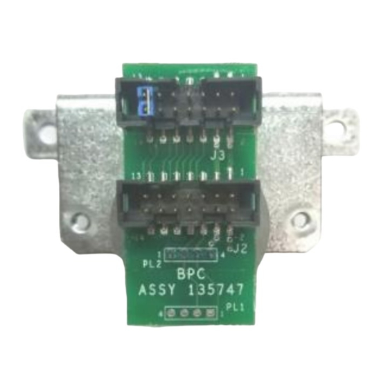
Bennett Pulser Assembly Instruction Manual Product Introduction PULSER ASSEMBLY ITEM DESCRIPTION Pulser Mount Pulser Circuit Board Assembly Pulser Top Cover Pulser Assembly PULSER ORIENTATIONS Top View Side View Main Components - Disassembled... - Page 9 Pulser D Phase 2 Bi-Directional Connection Verification Bi-Directional Connection Verification Bi-Directional Pulser Connector A 14-position ribbon cable header connection from the first pulser to the next pulser J2 connector. AWG & Color PIN # Signal Direction 5 VDC 5 VDC...
- Page 10 Bennett Pulser Assembly Instruction Manual Product Introduction Page Intentionally Left Blank...
-
Page 11: Section 3: Installation Instructions
HOW TO MOUNT THE PULSER ASSEMBLY The Pulser Assembly measures 4” x 2” x 2””. Each Pulser requires two mounting screws for the mount, and 2 mounting screws for the cover to the mount. Mount Pulser by aligning roll pin in coupler slot. - Page 12 Pulser for Product B plugs directly into Product A’s Pulser J2 = Pulser A J3 = Shunt on Pins 13-14 IMPORTANT: Jumper must be in place on the last pulser in series for any for pulser to work properly.
-
Page 13: How To Operate The Pulser
J2 (front) connector and it works like this for the remaining pulsers except for the last pulser for that side in the loop. Note: On the last pulser, a jumper must be placed across the last set of pins on J3 to identify that pulser as the last pulser in the loop. -
Page 14: Section 4: Diagnostics & Troubleshooting
To place an order for parts please contact us by mail, email, phone, fax, or web using the information provided below. Note: Verbal orders cannot be accepted. A signed purchase order must be faxed or emailed to the Bennett Order Entry Department at 231-799-6202 or customerservice@bennettpump.com. - Page 15 Bennett Pulser Assembly Instruction Manual Diagnostics & Troubleshooting Page Intentionally Left Blank...
-
Page 16: Section 5: Wiring Diagrams
Bennett Pulser Assembly Instruction Manual Wiring Diagrams SECTION 5: WIRING DIAGRAMS... - Page 17 Bennett Pulser Assembly Instruction Manual Wiring Diagrams...
- Page 18 Bennett Pulser Assembly Instruction Manual Page Intentionally Left Blank...
- Page 19 Bennett 1218 E. Pontaluna Road, Spring Lake, MI 49456 USA 800-235-7618 ~ Outside USA 231-798-1310 sales@bennettpump.com ~ www.bennettpump.com...
Need help?
Do you have a question about the PULSER and is the answer not in the manual?
Questions and answers