
Related Manuals for Electrolux WH6-20LAC

Summary of Contents for Electrolux WH6-20LAC
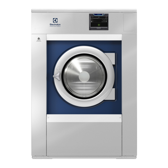
- Page 1 Installation manual Washer extractor WH6–20LAC, WH6–27LAC, WH6–33LAC Clarus Vibe Type W3..438905980/EN Original instructions 2022.08.09...
-
Page 3: Table Of Contents
Contents Contents 1 Safety Precautions ..........................5 General safety information......................6 Commercial use only........................6 Symbols............................6 2 Warranty terms and exclusions......................7 3 Technical data.............................8 WH6–20LAC, WH6–27LAC, WH6–33LAC...................8 Technical data ...........................9 Connections ..........................9 4 Setup ...............................10 Unpacking ..........................10 Recycling instruction for packaging ...................12 Siting ............................13 Mechanical installation ......................13 5 Water connection ..........................15 6 Water hardness and dosage.......................17... -
Page 5: Safety Precautions
Installation manual 1 Safety Precautions • Servicing shall be carried out only by authorized personnel. • Only authorized spare parts, accessories and consumables shall be used. • Only use detergent intended for water-wash of textiles. Never use dry cleaning agents. •... -
Page 6: General Safety Information
Installation manual – This appliance is not intended for use by persons (including children) with reduced physical, sensory or mental capabilities, or lack of experience and knowledge, unless they have been given supervision or instruction concerning use of the appliance by a person responsible for their safety. -
Page 7: Warranty Terms And Exclusions
Warranty will be applicable where the customer has used only genuine spare parts and has performed maintenance in accordance with Electrolux Professional user and maintenance documentation made available in paper or elec- tronic format. Electrolux Professional strongly recommends using Electrolux Professional approved cleaning, rinse and descaling agents to obtain optimal results and maintain product efficiency over time. -
Page 8: Technical Data
Installation manual 3 Technical data 3.1 WH6–20LAC, WH6–27LAC, WH6–33LAC fig.X01115B Display Door opening, WH6–20LAC, WH6–27LAC, WH6–33LAC: ⌀ 435 mm Detergent container Cold water Hot water Cold/Hot water Re-used water Drain valve Liquid detergent supply Electrical connection Steam connection WH6– 1415 1480 1135 20LAC... -
Page 9: Technical Data
Installation manual 3.2 Technical data WH6–20LAC WH6–27LAC WH6–33LAC Weight, net Drum volume litres Drum diameter Drum speed during wash Drum speed during extraction 1055 1007 1007 G-factor, max. Heating: Electricity Heating: Steam Heating: Hot water Frequency of the dynamic force 17.6 16.8 15.8... -
Page 10: Setup
Installation manual 4 Setup 4.1 Unpacking Removal of the bolts between the machine and pallet Note! Two persons are recommended for the unpacking. Remove the side panels. Remove the front and rear panel. fig.X01123 Remove the bolts between the machine and pallet. fig.X01124 Remove the machine from the pallet. - Page 11 Installation manual Removal of the transport securities When the machine is placed in final or close to final position, remove the four transport supports. Save the transport supports if the machine needs to be moved in the future. Note! Once the transport supports have been removed, handle the machine carefully to avoid damage to the sus- pension components.
-
Page 12: Recycling Instruction For Packaging
Installation manual 4.2 Recycling instruction for packaging fig.X02400 Fig. Description Code Type Wrapping film LDPE 4 Plastics Corner protection PS 6 Plastics Cardboard packaging PAP 20 Paper Pallet FOR 50 Wood Screw FE 40 Steel FE 40 Steel Plastic bag PET 1 Plastics... -
Page 13: Siting
Installation manual 4.3 Siting Install the machine close to a floor drain or open drain. The machine should be positioned so that there is plenty of room for working, both for the user and service personnel. The figure shows minimum distance to a wall and/or other machines. Failure to respect the prescribed distances will prevent easy access for maintenance and service operations. - Page 14 Installation manual Place the machine over the two drilled holes. The holes are at the front of the machine. Level the machine with the feet of the machine. Screw in the feet as much as possible before starting to level the ma- chine.
-
Page 15: Water Connection
Installation manual 5 Water connection All water intake connections to the machine should be fitted with manual shut-off valves and filters, to facilitate instal- lation and servicing. Water pipes and hoses should be flushed clean before installation. The machine shall be connected with new water hoses. Re-used water hoses must not be used. Hoses are to be of an approved type and grade and comply with IEC 61770. - Page 16 Installation manual For WRAS-approved machines; always check connection requirements on WRAS website. For KIWA-approved machines; always check connection requirements on KIWA website. For NSF-approved machines; always check connection requirements on NSF website. Plumbing This machine is approved for all UK applications as suitable for category 5. The product is listed in the WRAS regulations advisory scheme directory and is suitable for direct connection to mains drinking water.
-
Page 17: Water Hardness And Dosage
Installation manual 6 Water hardness and dosage Check the water hardness at your location and adjust the dosage according to the tables. The tables shows different dosage for different programs. A water hardness kit is available at Part No. 0S0586. 6.1 WH6–20LAC WH6–20LAC with full lagoon load (14 kg) Water hardness range... -
Page 18: Wh6-27Lac
Installation manual 6.2 WH6–27LAC WH6–27LAC with full lagoon load (19 kg) Water hardness range Water softener W01 - Lagoon Sensitive Detergent Program Wool High/Medium With weighing °D °F °E Dosage ml/kg Dosage ml/full load 0–5 0–9 0–6 0–90 Not required 5–10 9–18 6–12... -
Page 19: Wh6-33Lac
Installation manual 6.3 WH6–33LAC WH6–33LAC with full lagoon load (23 kg) Water hardness range Water softener W01 - Lagoon Sensitive Detergent Program Wool High/Medium With weighing °D °F °E Dosage ml/kg Dosage ml/full load 0–5 0–9 0–6 0–90 Not required 5–10 9–18 6–12... -
Page 20: Connection Of External Dosing Systems
Installation manual 7 Connection of external dosing systems Depending on which type of dosing system that is going to be connected, follow the instructions enclosed with the dosing system. The following is some preparations that can be made on the machine. 7.1 Jetsave and Dosave 7.1.1 Connection of the tube... -
Page 21: Drain Connection
Installation manual 8 Drain connection Connect a 75 mm pipe or rubber hose to the machine’s drain pipe, ensuring a downward flow from the machine. Avoid sharp bends which may prevent proper draining. The machine may drain in to a drainage through or into a closed drain system. In either case, be sure to comply with all applicable national and local plumbing code provisions. -
Page 22: Electrical Connection
Installation manual 9 Electrical connection 9.1 Electrical installation The electrical installation may only be carried out by qualified personnel. Machines with frequency-controlled motors can be incompatible with certain types of earth leakage circuit break- er. It is important to know that the machines are designed to provide a high level of personal safety, which is why items of external equipment such as earth leakage circuit breakers are not necessary but is recommended. -
Page 23: Electrical Connections
Installation manual 9.2 Electrical connections WH6–20LAC Heating alternative Main voltage Heating power Total power Recommended fuse Electric heated 220-240V 3 ~ 50/60 18.0 18.3 380-415V 3N ~ 50/60 18.0 18.3 440V 3 ~ 18.0 18.4 480V 3 ~ 18.0 18.4 Non heated/Steam 220-480V 1 ~ 50/60... -
Page 24: Machine Connection With Ferrite
Installation manual 9.3 Machine connection with ferrite 9.3.1 WH6–20LAC, WH6–27LAC, WH6–33LAC To obtain approved level of EMC, it is mandatory to use the ferrite which is enclosed with above listed models. (Note that this is only valid for those models). Before connecting to the machine, the protective earth (PE) wire shall be wrapped around the ferrite. -
Page 25: Machine Connection
Installation manual 9.4 Machine connection Connect the earth and other wires according to the table. Single-phase connection Three-phase connection 1NAC L2 L3 3N AC L2 L3 1N/1 3N AC L2/N Single phase machines may be powered either by connection between a phase and neutral or by connecting be- tween two phases. -
Page 26: Removal Of The Connector
Installation manual 9.5 Removal of the connector If no external dosing systems shall be connected to the machine the enclosed connector with termination resistor must be connected at the rear of the machine. • Connect the connector with termination resistor to connection B. fig.X01168A... -
Page 27: Steam Connection
Installation manual 10 Steam connection Inlet pipes connected to the machine must be equipped with a manual shut-off valve to facilitate installation and serv- icing. The connection hose must be of type ISO/1307- 1983 or equivalent. Connection size at filter: DN 15 (BSP 1/2"). Demount the top panel (A). -
Page 28: At First Power Up
Installation manual 11 At first power up When the installation is complete and the power is connected for the first time you will be forced to make some set- tings. Follow the instructions on the display. When one setting is ready you will automatically enter the next one. If installation is made in a public area, it is only allowed to select the below segmets: APARTMENT AUTO DOSING APARTMENT MANUAL DOSING... -
Page 29: Function Check
Installation manual 12 Function check May only be carried out by qualified personnel. A function check must be made when the installation is finished and before the machine can be ready to be used. Open the manual water valves. Start a program. •... -
Page 30: Disposal Information
Installation manual 13 Disposal information 13.1 Disposal of appliance at end of life Before disposing of the machine, make sure to carefully check its physical condition, and in particular any parts of the structure that can give or break during scrapping. The machine’s parts must be disposed of in a differentiated way, according to their different characteristics (e.g. - Page 32 Electrolux Professional AB 341 80 Ljungby, Sweden www.electroluxprofessional.com...
Need help?
Do you have a question about the WH6-20LAC and is the answer not in the manual?
Questions and answers