Table of Contents
Advertisement
Quick Links
Advertisement
Table of Contents

Subscribe to Our Youtube Channel
Summary of Contents for RUNZEL LM60A
- Page 1 http://www.runzeliuti.com...
-
Page 2: Table Of Contents
Table of Contents Chapter 1 Product Introduction....................4 1.1 Overview............................. 4 1.2 Product Features..........................4 Chapter 2 Instruction of Port and Structure................5 2.1 Technical Parameters........................5 2.2 Overall Structure Diagram........................5 2.3 Definition of Communication Interface................... 6 2.4 Pump Head/Tube Selection......................6 2.5 Special Function Switching...................... - Page 3 4.2 Setting Command (suitable for factory command format)............15 4.3 Query Command(suitable for common command format)..........16 4.4 Control command(suitable for common command format)..........16 4.5 Communication Control Mode Interface..................17 4.5.1 Control command (example)....................17 4.5.2 Status query command (example)..................17 4.5.3 Set command (factory command) and query (example)..........17 Chapter 5 External Control Mode.....................
-
Page 4: Chapter 1 Product Introduction
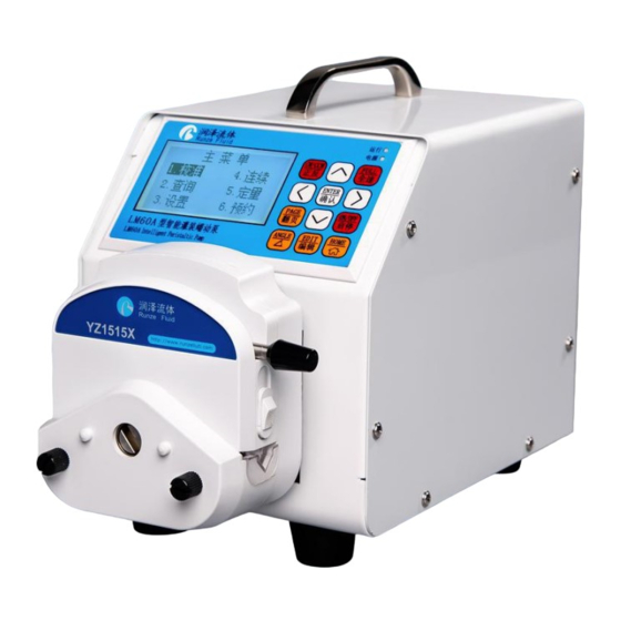
Chapter 1 Product Introduction 1.1 Overview LM60A intelligent filling peristaltic pump, using high-performance processor and motor drive, controlling stepper motor, motor subdivision adaptive, the minimum speed can reach 0.1rpm; rich application scenarios, support keyboard control mode, communication control mode (RS232 /RS485), external control mode (optional multiple signal conversion modules);... -
Page 5: Chapter 2 Instruction Of Port And Structure
DC24V±10% Power consumption Working environment temperature 0-40 ℃, relative humidity < 80% Dimensions (unit: mm) 218 (length) × 148 (width) × 199 (height) Weight 3.5 kg Protection grade IP31 2.2 Overall Structure Diagram Figure 2-2 Structure diagram of LM60A http://www.runzeliuti.com... -
Page 6: Definition Of Communication Interface
2.3 Definition of Communication Interface Item Description +24V DC24V Power Supply RS232 Data output RS232 Data input Passive contact output - common port +5V Power supply Passive contact output –common close port Passive contact output –common open port FT_EXST Foot pedal/ external start stop signal input port Ground wire EX_DIR External steering signal input port... -
Page 7: Special Function Switching
hardness will lead to difference of flow rate, so the maximum flow rate is only for reference. (3) When using a tube with thicker wall (such as 24# tube), the current can be set to be larger, so as to increase the torque of the pump at high speed. (4) When using a tube with thicker wall (such as 24# tube), the pump might be stalled when it starts at high speed after stopping working for a period of time. -
Page 8: Chapter 3 Keyboard Control Mode
Chapter 3 Keyboard Control Mode 3.1 Main Menu Figure 3-1 The main menu The main menu shows six functions, "Calibration", "Continuous", " Rationing ", "Booking", "Query" Setting". On the main menu, you can press "up", "down", "left" and "right" keys to switch functions. On the main menu, when a function is displayed reversely, press the "Enter"... - Page 9 and input the calibration result. The specific calibration process is as follows: YZ1515X-6 rollers Intersection point Figure 3-2-1 Use of flow curve table (1) Determine calibration speed. According to the flow rate you need, query the flow curve of the corresponding pump head / tube (Chapter 6 flow curve) to obtain the approximate calibration speed.
-
Page 10: Inquiry Mode
appropriately. Repeat the test for many times to obtain the average value of the liquid volume obtained from multiple calibrations, which can improve the accuracy of the calibration results. Figure 3-2-2 Editing and process of calibration 3.2.2 Inquiry Mode Parameters such as standard speed, standard flow, minimum flow, maximum flow and standard ratio can be queried. -
Page 11: Setting Mode
automatically calculates the minimum flow 3.2.2.4 Maximum flow According to the calibrated speed, maximum speed and calibrated flow, the system automatically calculates the maximum flow. 3.2.2.5 Calibration ratio Calibration ratio = calibrated flow / calibrated speed. Calibration ratio unit: ml / r. This is a reference unit for calculation. -
Page 12: Continuous Mode
Definition table of current code as below: Maximum motor Effective motor Maximum motor Effective motor Current Current Code output current output current output current output current Code (A) (A) (A) (A) 1.000 0.700 2.625 1.840 1.125 0.790 2.750 1.925 1.250 0.875 2.875 2.013... -
Page 13: Rationing Mode
speed / flow. 3.2.5 Rationing Mode In rationing mode, the machine has been through the normal calibration process by default. (1) On the main menu, select "Rationing" and press "Edit" to enter the rationing editing interface. On the main menu, select " Rationing " and press "Enter" to enter rationing standby interface. (2) On the rationing editing interface, input the required liquid volume and time, and press "Enter"... -
Page 14: Chapter 4 Communication Control Mode
Chapter 4 Communication Control Mode 4.1 Command Format 4.1.1 Common Command Format (send 10 bytes, return 10 bytes) Byte send: FH (Frame Address Function EOF (End Function parameters Cumulative sum header) code code of frame) ADDR FUNC 1-8 bit 9-16 bit 17-24 bit 25-32 bit Low byte High byte The 1 byte STX: frame header (CCH) -
Page 15: Setting Command (Suitable For Factory Command Format)
The 1 byte STX: frame header (CCH) The 2 byte ADDR: slave address (01H~ F7H) The 3 byte FUNC: function code The 4-7 bytes: password of factory command The 8 bytes: parameters corresponding to the function code The 12 byte ETX: end of frame (DDH) The 13 bytes: cumulative sum check code from byte 1 to 12 Byte return:... -
Page 16: Query Command(Suitable For Common Command Format
10 times storage; fixed Set maximum 00000001H~0000FA0H parameters (1~4000); default speed (0.1~400.0rpm) 3000 Table 4-2 List of setting command 4.3 Query Command(suitable for common command format) Serial Functio Function Parameter Remark number n code The slave does not recognize the command address, and when one more Query the device address No parameter device with RS485, the query address has... -
Page 17: Communication Control Mode Interface
The returned status Forced to stop random parameter is 0. Return current status. Query motor status(Number of random The parameter is the steps left) number of steps left. 0001H~FA0H 10 times the actual Set dynamic speed (0.1rpm~400.0rpm) speed value Return 10 times the Query dynamic speed random dynamic speed... -
Page 18: Chapter 5 External Control Mode
Chapter 5 External Control Mode 5.1 External Speed Control Operation (1) Press and hold the "right" key to switch to external control mode. The default is in the stop state of the external control mode. (2) Press the "ON/OFF" on the keyboard or the middle button of the rotary encoder to switch between start and stop. -
Page 19: Maximum Speed Setting
rotation, and setting EXST low (short circuit with ground) allows rotation. (7) External speed control input port ADC-IN can adjust signal. The port voltage is 0 ~ DC3.3V. If you want to input other speed control signals, the corresponding signal converters need to be connected for correct operation. -
Page 20: Chapter 6 Technical Parameters Of Peristaltic Pump Tube
0.17 0.14 0.10 0.17 Pressure (Mpa) Short 0.27 0.24 0.14 0.27 Table 6-1 table of commonly used flexible tube 6.2 Peristaltic Pump Head-Tube Reference Flow Curve (1) YZ1515X-3 rollers (LM60A) flow-speed curve Figure 6-2-1 YZ1515X-3 rollers (LM60A) flow-speed curve http://www.runzeliuti.com... - Page 21 (2) YZ1515X-6 rollers (LM60A) flow-speed curve Figure 6-2-2 YZ1515X-6 rollers (LM60A) flow-speed curve (3) YZ2515X-3 rollers (LM60A) flow-speed curve Figure 6-2-3 YZ2515X-3 rollers (LM60A) flow-speed curve (4) SN15-3 rollers (LM60A) flow-speed curve http://www.runzeliuti.com...
- Page 22 Figure 6-2-4 SN15-3 rollers (LM60A) flow-speed curve (5) SN15-6 rollers (LM60A) flow-speed curve Figure 6-2-5 SN15-6 rollers (LM60A) flow-speed curve (6) SN25-3 rollers (LM60A) flow-speed curve Figure 6-2-6 SN25-3 rollers (LM60A) flow-speed curve Note 1: The above "Flow-Speed" of different pump heads and different tubes is the actual test curve, without any modification, for reference only;...
-
Page 23: Chapter 7 Equipment Maintenance
Chapter 7 Equipment Maintenance 7.1 Common Equipment Maintenance Process 1. Regular maintenance of tube When the tube is not used for a long time, please empty the liquid in the tube in time, open the protective lock on the pump head and loosen the pump tube. 2. - Page 24 Check whether the pump body joint is loose and reliable. Check whether the current code in “settings” is too Motor The screen shows that the motor small. Set the current code consistent with the does not works. In fact, the motor does not product.
-
Page 25: Chapter 8 Version Introduction
Chapter 8 Version Introduction Version Description Release time V1.0 Initial version 2019-09-27 1. Add the corresponding table of current code 2. Correct the maximum speed of the motor V1.1 corresponding to the tube 2020-02-28 3. Modify the expression of "inquiry / setting / continuous mode". -
Page 26: Chapter 9 Technical Service
Chapter 9 Technical Service http://www.runzeliuti.com...
Need help?
Do you have a question about the LM60A and is the answer not in the manual?
Questions and answers