
Related Manuals for fiac AIRBLOK 40


Summary of Contents for fiac AIRBLOK 40
- Page 1 USE AND MAINTENANCE MANUAL SILENT ELECTRIC ROTARY SCREW COMPRESSORS WARNING: Read this manual carefully and in full before using the compressor. 1/68...
- Page 2 IMPORTANT INFORMATION Read all the operational instructions, safety recommendations and all warnings provided in the instruction manual. Most accidents encountered when using the compressor are merely due to the failed observance of basic safety standards. Accidents are prevented by foreseeing potentially hazardous situations and observing the appropriate safety standards.
-
Page 3: Table Of Contents
INDEX Index Foreword ..................5 How to read and use the instruction manual ..........5 0.1.a Importance of the manual ....................5 0.1.b Conserving the manual ......................5 0.1.c Consulting the manual ......................5 0.1.d Symbols used ........................6 General information................ 7 Identification data of the manufacturer and the compressor .... - Page 4 INDEX Starting the compressor................29 Stopping the compressor ................30 Compressor maintenance............31 Instructions relative to inspections and maintenance jobs....31 6.1.1 Changing the oil ........................33 6.1.2 Replacing the oil filter cartridge ..................34 6.1.3 Replacing the filter cartridge of the oil separator ............34 6.1.4 Replacing the air filter cartridge ..................
-
Page 5: Foreword
FOREWORD Foreword How to read and use the instruction manual 0.1.a Importance of the manual This INSTRUCTION MANUAL has been written to guide you through the INSTALLATION, USE and MAINTENANCE of the compressor purchased. We recommend that you strictly observe all the indications given within as the ideal operational efficiency and lasting wear of the compressor depend on the correct use and methodical application of the maintenance instructions given hereafter. -
Page 6: Symbols Used
FOREWORD 0.1.d Symbols used The SYMBOLS pointed out below are used throughout this manual and their purpose is that of drawing the operator’s attention, informing the latter how to behave and how to proceed in each operational situation. READ THE INSTRUCTION MANUAL Read the use and maintenance manual carefully before installing and starting the compressor. -
Page 7: General Information
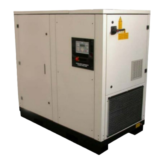
GENERAL INFORMATION General information Identification data of the manufacturer and the compressor COMPRESSOR IDENTIFICATION NAMEPLATE (Example) Silent electric rotary screw compressor. Information on machine technical/maintenance service We remind you that our technical service department is at your complete disposal to help you resolve any problems that may possibly be encountered, or to provide you with any other information necessary. - Page 8 GENERAL INFORMATION 2. NEVER USE THE COMPRESSOR WITHOUT THE SAFETY GUARDS FITTED Never use the compressor without all the safety guards fitted perfectly in their correct place (i.e. panelling, belt guard, safety valve). If these parts are to be removed for maintenance or servicing purposes, ensure that they are put back in their original place perfectly before using the compressor again.
- Page 9 GENERAL INFORMATION 18.ENSURE THAT EACH SCREW, BOLT AND GUARD IS FIRMLY SECURED IN PLACE. 19.KEEP THE IN-TAKE GRIDS CLEAN Keep the motor ventilation grids clean. Regularly clean these grids if the work area is particularly dirty. 20.OPERATE THE COMPRESSOR AT THE RATED VOLTAGE Operate the compressor at the voltage specified on the electrical data nameplate.
-
Page 10: Preliminary Machine Information
Therefore it is extremely important to choose the correct type of oil for this type of compressor. NEVER MIX DIFFERENT OIL QUALITIES. SCREW OIL FOR DR/SD VERSIONS FIAC SYNT/RS D 46 OR IN ALTERNATIVE SHELL... -
Page 11: Technical Data
PRELIMINARY MACHINE INFORMATION 11/68... -
Page 12: Transport, Handling, Storage
PRELIMINARY MACHINE INFORMATION Transport, Handling, Storage In order to use the compressor in complete safety read the safety standards given in section 1.3. before reading this section. Transporting and handling the packed machine The packed compressor must be transported by qualified personnel using a forklift truck. -
Page 13: Storing The Packed And Unpacked Compressor
PRELIMINARY MACHINE INFORMATION Using a forklift truck take the compressor as near as possible to the place where it is to be installed then carefully remove the protective packing without damaging it, following the instructions below: • Remove the securing screws and open cage 1. •... -
Page 14: Installation
INSTALLATION Installation In order to use the compressor in complete safety read the safety standards given in section 1.3. before reading this section. Admitted surrounding conditions Position the machine as established when the order was placed. Failing this the Manufacturer is not liable for any inconveniences that may possibly arise. -
Page 15: Positioning The Compressor
INSTALLATION H. min = 3500 min. 1000 2000 min. 5000 Ducts for the inlet and outlet of the air can be used in unfavourable environments. These ducts must be the same size as the in-take and delivery grid. If these ducts are longer than 3 meters contact the Authorised Service Centre. -
Page 16: Connecting The Compressor To The Sources Of Energy And Relative Inspections
INSTALLATION Connecting the compressor to the sources of energy and relative inspections. 4.4.1 Connecting the compressor to the electrical mains power supply The compressor is to be connected to the electrical mains by the customer, to his exclusive liability, employing specialised personnel and in compliance with the Accident Prevention Norms EN 60204. - Page 17 INSTALLATION for SD models: Power Hp Rated voltage 380/415V 220/415V Magneto thermal switch Fuse Magneto thermal switch Fuse 100A 125A Note! The parameters of the magneto thermal switches refer to switches type K. Ensure the installed power in kW is at least double the input of the electric motor, for SD models, the installed power in kW must be the same as that absorbed by the compressor.
-
Page 18: Connecting The Dryer To The Electrical Mains
INSTALLATION 4.4.2 Connecting to the pneumatic mains Always use pneumatic hoses for compressed air with the maximum pressure characteristics and cross section suitable for those of the compressor. Do not try to repair a faulty hose. Connect the compressor to the pneumatic mains using the fitting 1 pre-arranged on the compressor. Use hosing with a greater or same diameter as the compressor outlet. -
Page 19: Using The Compressor
USING THE COMPRESSOR Using the compressor In order to use the compressor in complete safety read the safety standards given in section 1.3. before reading this section. Preparing to use the compressor 5.1.1 Operational principle The air taken-in by the filter passes through a valve that controls its flow rate to the screw where, mixing with the oil, it is compressed. -
Page 20: Controls, Indicators And Safety Devices Of The Compressor
USING THE COMPRESSOR When the request for air is greater, therefore the line pressure drops, the inverter increases the speed of the motor, also increasing the air output. When the request for air is lower, the inverter reduces the speed of the motor, also reducing the air output, therefore the mains pressure is held constant as the air consumption varies. -
Page 21: Auxiliary Control Devices
USING THE COMPRESSOR 10 EMERGENCY PUSH BUTTON This mechanically blocking push button is used to immediately stop the compressor in the case of emergency. With the push button blocked it is impossible to start the compressor. To be able to start the compressor again, turn the emergency push button up then press the RESET button. - Page 22 USING THE COMPRESSOR CHECKING THE SETTINGS 1) When the machine is ready, “PRESS START TO START” appears on the display. You can check the overall setting of the control unit by pressing the “UP arrow” or DOWN arrow” keys of the push button control panel: Note! Refer to the menu descriptions to better comprehend the meaning of the parameters listed...
- Page 23 USING THE COMPRESSOR CLIENT MENU (“> + DEFAULT” simultaneously) To access this menu, press keys > and DEFAULT simultaneously. The CLIENT MENU enables you to calibrate the following parameters: 1. Cut-in pressure of the compressor (Min. P.) 2. Cut-off pressure of the compressor (Max. P.) 3.
- Page 24 USING THE COMPRESSOR To summarise: CALIBRATION LIMITS Max. P. < Alarm P. - 0.5 bar/7.2 psi Min. P. > 5.5 bar/79.8 psi DP = (Max. P. – Min. P.) > 1 bar/14.5 psi 120 s < IDLE RUNNING TIME < 600 sec “0”...
- Page 25 USING THE COMPRESSOR 3. When the electric motor of the radial fun overheats, the following appears on the display: THE COMPRESSOR STOPS! ALARM THERMIC To reset the machine: Wait for the temperature of the fan motor to cool down to normal conditions Once you have eliminated the overheating causes, press the “RESET”...
- Page 26 USING THE COMPRESSOR WARNING OIL SEPAR. FILTER This points out that the oil separator filter in the separator tank is clogged. Replace the filter as soon as possible. WARNING MAINTENANCE TIME This points out that the pre-established maintenance time has expired. Carry out the maintenance jobs stated herein.
- Page 27 USING THE COMPRESSOR Solution: Check for excessive static or transitory voltages in the mains. To restore machine operation: Eliminate the cause for the fault. Press the RESET button on the keypad of the ACS550 INVERTER inside the electric cabinet. Then press also the “RESET”...
- Page 28 USING THE COMPRESSOR STATUS WORD1: 00032 The dc voltage of the intermediary circuit is insufficient due to a missing mains phase, blown fuse or an internal fault of a rectifier bridge. THE COMPRESSOR STOPS! Solution: Check the mains power supply, the fuses and the power supply voltage. To restore machine operation: Eliminate the cause for the fault.
-
Page 29: Check The Efficiency Of The Safety Devices Before Starting
USING THE COMPRESSOR To restore machine operation: Eliminate the cause for the fault. Press the RESET button on the keypad of the ACS550 INVERTER inside the electric cabinet. Then press also the “RESET” key on the control board to set the compressor ready to start. STATUS WORD2: 02048 The motor nearly stalls, for example due to excessive loads or insufficient motor power. -
Page 30: Stopping The Compressor
USING THE COMPRESSOR Before initially starting the compressor or following extended inoperation, you need to start the machine intermittently by pressing the START(I)-STOP(O) buttons alternately for 3 or 4 seconds. It is then advisable to run the compressor for a few minutes with the air outlet tap open. Gradually shut-off the air tap and load to the maximum pressure, checking if the inputs on each phase of the electric power supply are within the limits and if the pressure on the display of the board is correct and if the maximum pressure set triggers compressor idle running mode. -
Page 31: Compressor Maintenance
COMPRESSOR MAINTENANCE Compressor maintenance In order to use the compressor in complete safety read the safety standards given in section 1.3. before reading this section. Instructions relative to inspections and maintenance jobs. The table that follows summarises the periodic and preventative maintenance jobs required to keep the compressor in an efficient operational state in time. - Page 32 COMPRESSOR MAINTENANCE Interval Jobs to be performed (hours) section weekly 6.1.9 Check if the filters of the electric cabinet are clogged (for versions SD) ... 6.1.7 Check if the anti-dust pre-filter is clogged ......500 hours following 6.1.1 Check the oil level ..............first start-up Check the electrical connections and tighten if necessary ..
-
Page 33: Changing The Oil
COMPRESSOR MAINTENANCE 6.1.1 Changing the oil Read all the information provided in Section 6.1 before proceeding with any maintenance jobs. Check the oil level after 500 hours of use and then every 5000 hours and in event once a year. Open the front panel to access the internal parts of the compressor. -
Page 34: Replacing The Oil Filter Cartridge
COMPRESSOR MAINTENANCE 6.1.2 Replacing the oil filter cartridge Read all indicated in Section 6.1 before starting any maintenance jobs. Replace the oil filter cartridge after the first 2500 hours and in any event each time the oil is changed. Open the front panel. Disassemble filter cartridge 1, using a chain spanner and replace with a new one. -
Page 35: Replacing The Air Filter Cartridge
COMPRESSOR MAINTENANCE 6.1.4 Replacing the air filter cartridge Read all indicated in Section 6.1 before starting any maintenance jobs. Open the top panel to access inside the compressor. Take the cover off 1; clean the filter holder thoroughly. Replace the cartridge of the air filter 2 and fit the cover back in place. 6.1.5 Joint On a periodic basis, visually inspect the joint 2 based on the hours of operation indicated in the maintenance... -
Page 36: Cleaning The Air/Oil Radiator
COMPRESSOR MAINTENANCE 6.1.6 Cleaning the air/oil radiator Read all indicated in Section 6.1 before starting any maintenance jobs. It is advisable to clean the radiator 1 on a weekly basis to remove impurities, blowing it with an air gun from inside. - Page 37 COMPRESSOR MAINTENANCE Replace the bearings This job is to be done by the Technical Service centre after carefully inspecting the bearings. It is advisable to replace the bearings after: 36.000 hours of operation if the compressor is used in normal conditions (ambient temperature up to 25°C). 20.000 hours of operation if the compressor is used in harsher conditions (ambient temperature up to 40°C).
-
Page 38: Diagnosing The Alarm Status/Inconveniences-Faults
COMPRESSOR MAINTENANCE 6.1.11 Cleaning the dissipator (only for version SD) Dust transported by the cooling air may settle on the fins of the dissipator. If the dissipator is not cleaned regularly, the drive may encounter alarms and faults due to overheating. In “normal” surroundings, the dissipator must be cleaned and inspected on a yearly basis, but more often in dusty surroundings. - Page 39 The machine works with two phases due a fault in the motor or due to a blown fuse, therefore have the motor repaired by an authorised Fiac SpA centre if necessary or replace the blown fuse. If the machine fails to depressurise, check the depressurisation...
- Page 40 COMPRESSOR MAINTENANCE Anomalies Cause Solution The machine stops, as the The pressure exceeds the Check the line pressure, release the pressure safety switch has alarm pressure. pressure to take it back to the set working tripped (red LED). values. The machine fails to start The screw unit and the motor Invert two phases of the power supply on when starting it up for the...
-
Page 41: Drawings And Diagrams
FINITO SCHEMA ELETT. COLL. POTENZA SCHEMA ELETT. COLL. POTENZA --- --- --- --- MACCHINA MACCHINA SCALA SCALA AIRBLOK 40 50SD 400V/50-60Hz AIRBLOK 40 50SD 400V/50-60Hz --- --- PROPRIETA’ RISERVATA PROPRIETA’ RISERVATA CODICE GREZZO CODICE GREZZO CODICE PARTICOLARE CODICE PARTICOLARE vietato copiare o divulgare... - Page 42 DRAWINGS AND DIAGRAMS 42/68...
- Page 43 DRAWINGS AND DIAGRAMS 43/68...
- Page 44 DRAWINGS AND DIAGRAMS 44/68...
- Page 45 DRAWINGS AND DIAGRAMS 45/68...
- Page 66 DRAWINGS AND DIAGRAMS 46/68...
- Page 67 Date Job description Hours of use Operator’s signature ......................................................................................................................................................................................................................................................
Need help?
Do you have a question about the AIRBLOK 40 and is the answer not in the manual?
Questions and answers
Hey hello