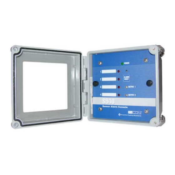
Summary of Contents for Franklin Fueling Systems INCON S940
- Page 1 S940 Sensor Alarm Console Installation and Operation Guide Franklin Fueling Systems • 3760 Marsh Rd. • Madison, WI 53718 USA Tel: +1 608 838 8786 • 800 225 9787 • Fax: +1 608 838 6433 • www.franklinfueling.com...
- Page 2 Visually inspect all components for defects or damage prior to installation. If any defect or damage is found, do not use the product and contact FFS for further assistance. Return Shipping Charges FFS will not accept shipments of returned products without a Return Goods Authorization (RGA) number. RGAs are obtained by contacting FFS’s Technical Service Division — NO RGAs will be given without the unit’s serial number(s). Returned material remains the property of the buyer until replaced or repaired. Under Warranty FFS will pay all freight and insurance charges for all “Under-Warranty” RGAs. Non-Warranty It is the buyer’s responsibility to prepay all freight and insurance charges for “Non-Warranty” RGAs. Refer to the Warranty document FFS-0079. Contacting Franklin Fueling Systems (FFS) Please feel free to contact us by mail at: Franklin Fueling Systems 3760 Marsh Rd. Madison, WI 53718 USA Or contact us by phone, fax or e-mail: Tel: 1 608 838 8786 E-mail: sales@franklinfueling.com Fax: 1 608 838 6433 techserve@franklinfueling.com Tel: US & Canada 1 800 225 9787 Tel: México 001 800 738 7610 Tel: Europa +49 6571 105 380...
-
Page 3: Table Of Contents
Contents Important Safety Messages ....................... 1 Introduction ........................... 2 Product Description ........................2 Installation ............................2 Operation ............................3 Programming ..........................3 Control Drawing ..........................4... -
Page 4: Important Safety Messages
Important Safety Messages INCON equipment is designed to be installed in association with volatile hydrocarbon liquids such as gasoline and diesel fuel. Installing or working on this equipment means working in an environment in which these highly flammable liquids may be present. Working in such a hazardous environment presents a risk of severe injury or death if these instructions and standard industry practices are not followed. Read and follow all instructions thoroughly before installing or working on this, or any other related, equipment. As you read this guide, please be aware of the following symbols and their meanings: This symbol identifies a warning. A warning sign will appear in the text of this document when a potentially Warning hazardous situation may arise if the instructions that follow are not adhered to closely. A potentially hazardous situation may involve the possibility of severe bodily harm or even death. This is a caution symbol. A caution sign will appear in the text of this document when a potentially hazardous Caution environmental situation may arise if the instructions that follow are not adhered to closely. A potentially hazardous environmental situation may involve the leakage of fuel from equipment that could severely harm the environment. This symbol identifies an electrical danger. An electrical danger sign will appear in the text of this document Danger when a potentially hazardous situation involving large amounts of electricity may arise if the instructions that follow are not adhered to closely. A potentially hazardous situation may involve the possibility of electrocution, severe bodily harm, or even death. Follow all applicable codes governing the installation and servicing of this product and the Warning entire system. -
Page 5: Introduction
Introduction Installation Mounting This manual contains installation instructions for the To mount the unit to the wall, first attach the included INCON S940 Alarm Console. mounting tabs to the box (figure 1) and then attach it to Please carefully read this entire manual. Failure to the wall. follow the instructions in this manual may result in faulty operation, equipment damage, injury or death. This equipment should only be serviced by an FFS- certified technician. Product Description The 4-channel Alarm console is a stand-alone unit that monitors 4 intrinsically safe sensor contact closures and provides a visual and audible alarm should one of the normally closed contacts become open. The unit also provides 2 SPDT dry relay contacts that can be set to activate upon an alarm condition. Figure 1: Box Mounting Tab The S940 is typically used to monitor sumps, overfill or spill-containment areas. Power Supply Wiring Specifications NOTE: The S940 Alarm Console is set to operate with between 100 to 240 VAC, 50 / 60 Hz. No setup is required. Console Specifications The Alarm Console must be connected to a dedicated circuit breaker, at the service panel, not exceeding 15 Amps. Input Line Voltage: 100-240 VAC + / - 10%, 50 / 60 Hz, 15W max Input power fuse ... -
Page 6: Operation
Programming 1. Connect the right ground terminal to the earth ground bus at the service panel. Use #14 AWG The settings for the DIP switches in figure 3 determine copper conductor wire. which output relay is triggered in response to particular 2. Connect the left ground terminal to the metal rigid sensor inputs and the type of audible alarm transmitted. conduit used to feed service panel wiring with #14 AWG copper conductor wire. Relay 1 Activation and Sensor Assignment 3. Connect power wires to the appropriate terminals Switch Affected Sensor on the power supply terminal strip: Ground, Line, Switch Position Neutral, Earth Ground. Sensor 1 triggers Relay 1 Sensor Wiring Sensor 2 triggers Relay 1 All sensor wiring is to be intrinsically Warning 3 Sensor 3 triggers Relay 1 safe and run into the right side of the wiring bay and be fully contained... -
Page 7: Control Drawing
Control Drawing... - Page 8 ©2012 FFS 000-2147 Rev. C...


Need help?
Do you have a question about the INCON S940 and is the answer not in the manual?
Questions and answers