
Related Manuals for EMRAX 188


Summary of Contents for EMRAX 188
- Page 1 EMRAX d.o.o. Molkova pot 5 1241 Kamnik Slovenija, EU Motor Installation and Maintenance Manual For additional information’s turn to: support@emrax.com All data found in this manual is subject to change without notice.
- Page 2 Installation and Maintenance Manual V Notes: This page intentionally left blank.
-
Page 3: Table Of Contents
Installation and Maintenance Manual V Contents 1. General information ............................4 1.1. How to properly use this manual ...................... 4 1.2. Safe motor operation information ....................4 1.3. Intended use ............................5 1.4. Operating ceiling ..........................5 1.5. Description of nameplate ........................5 1.6. -
Page 4: General Information
These instructions do not purport to cover all the details in motors nor to provide for every possible contingency to be met in connection with installation, operation, or maintenance. Should further information be desired, or should problems arise which are not covered sufficiently for the purchaser’s purposes, the matter should be referred to EMRAX directly. -
Page 5: Intended Use
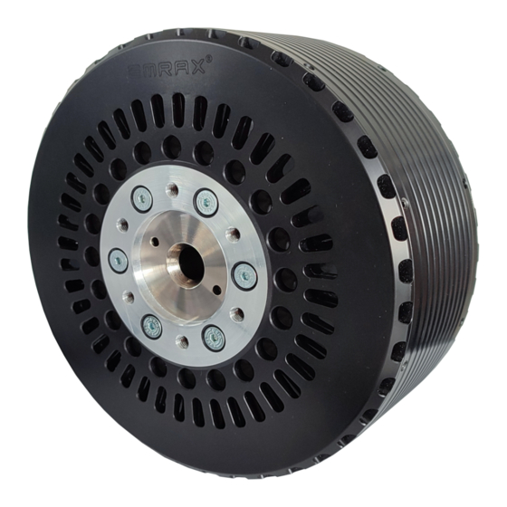
Electrical motor will convert electrical energy into mechanical rotating energy or vice versa. Its primary Every motor that is manufactured by EMRAX has a usage is found in aviation, but not limited to. The model and a serial number, which are permanently marked on the motor nameplate. -
Page 6: Handling
Installation and Maintenance Manual V If the resistance is lower than 1 Giga-ohm the windings should be dried in one of the two following ways: 1) Bake in oven at temperatures not exceeding 90 ⁰C until insulation resistance becomes constant. 2) With rotor locked, apply low voltage, and gradually increase current through windings until temperature measured with thermometer... -
Page 7: Sensor Mounting
(this step is only required for the 268 and 348 Depending on the application, a motor position sensor motor types). Before inserting the part use may be required. EMRAX offers a variety of different threadlocker glue on the faces, where the positioning sensors that can be supplied together with parts are mated. -
Page 8: Tamagawa Resolver Installation
Installation and Maintenance Manual V 6. Tighten the tapered bolt (7). 7. Mount the RLS RM44 encoder (3), to the mounting flange of the encoder bracket (2). Use the supplied M4x16 bolts (2), to mount the encoder. Using threadlocker glue on the threads is recommended. -
Page 9: Motor Installation
Installation and Maintenance Manual V 3. Motor installation 4. Mount the resolver bracket (1) on the back of the motor. Make sure that it is seated in its position, if necessary, use temporary bolts to tighten it to the motor. (If the motor is liquid 3.1. -
Page 10: Mounting The Motor
Installation and Maintenance Manual V 3.2. Mounting the motor Motors should be mounted on firm flat base with 4 bolts (highlighted) via X bracket bought with the motor: Figure 10: Highlighted mounting plate When bolting the motor, take care to permit a minimum of 1.5 * bolt diameter thread turns to protrude inside the flange. -
Page 11: Motor Output
Custom flange can be manufactured, or a flanged of hammers leaves blemishes on the bearing races. shaft (FSI) can be bought from EMRAX. Please find a These initially small flaws increase with usage and table with appropriate bolts and required torque for can develop to a stage that completely impairs the tightening them under twin installation chapter. -
Page 12: Twin Motor Assembly
Bolt size and Torque Qty. size length [Nm] M6x20 EMRAX can supply parts necessary to combine two M8x25 motors to form a twin motor configuration. M8x25 M8x30 A twin motor configuration consists of two motors: M10x35 Motor with extended shaft (ESO) (Front motor) 2. -
Page 13: Motor Cooling
3.5. Motor cooling continuous duty cycle of the motors to be much lower. Please refer to EMRAX support on advice In case of using liquid or combined cooled motor regarding your application. (LC/CC), coolant needs to be supplied to the motor at... -
Page 14: Temperature And Sensor Connection
Installation and Maintenance Manual V To install the fittings to the motor: The use of electro-insulating gloves is recommended, 1. Grease and install the O-ring onto the coolant when dealing with high voltage electrical connections. fitting 2. Press the fitting into the cooling channels of Using an IMD (insulation monitoring device), when the motor, while gently rotating it from side to using voltages higher than 48V is advisable. -
Page 15: Steps Prior To Starting
2 bar(g) mounting and alignment. If the issue is not resolved, is used, and that the temperature never please contact EMRAX support for further exceeds 90 ⁰C. instructions. -
Page 16: Bearings
EMRAX will not be liable for any costs or damage incurred by its customers in the removal or replacement of defective products from units in which 5.7. - Page 17 Installation and Maintenance Manual V Document Revision history: Revision Date Author Description________________________________ 06/12/2021 U.K. Initial version 22/12/2021 U.K. Revised nameplate and motor cooling 21/02/2022 U.K. Updated pressure drop values 09/03/2022 U.K. Added warranty claim, revised 2.6 and 2.4 19/10/2022 Revised manual, added installation instructions...
Need help?
Do you have a question about the 188 and is the answer not in the manual?
Questions and answers