Table of Contents

Summary of Contents for Ronald N53AB52
- Page 1 UFODAS Unidentified Flying Object Data Acquisition System Systems for the UFO Data Acquisition Project (UFODAP) ufodap.com System Installation Guide Revised 10-10-22 Version 1.08 Copyright © 2022 Ronald Olch RHOlch Systems...
- Page 2 — please watch out for these and report any you find to the developer at team.ufodap@gmail.com. Contributions of material, suggestions and corrections are welcome. Copyright © 2022 Ronald Olch All rights reserved. THIS INFORMATION IS PROVIDED BY THE COPYRIGHT HOLDER ON AN “AS IS”...
-
Page 3: Table Of Contents
System Power Requirements and Sources ....................9 Dome Camera Preparation ........................12 Tripod Installations for Cameras ......................14 Dahua 50230 or 42212 Camera setup ....................14 Dahua N53AB52 camera setup ....................... 16 Fixed Camera Installation......................... 18 Pole or corner mounting .......................... 18 Wall mounting ............................21 MSDAU Installation ........................... - Page 4 PC hardware selection ..........................61 Tracking problems ........................... 62 Camera setup for focus and zoom ......................62 Testing OTDAU setup and tracking ......................63 System setup for triangulation ......................... 65 Initial camera and MSDAU setup and test ....................65 Initial camera connection and testing ...................... 66 Can a camera be used with other software as well as OTDAU and MC at the same time? ....
-
Page 5: Introduction
INTRODUCTION A data collection system configured as part of the UFO Data Acquisition Project (UFODAP) utilizes UFO Data Acquisition System (UFODAS) components. A UFODAS consists of a number of hardware and software components including cameras, cables, a Power over Ethernet (PoE) Injector and software. This document will guide you through the initial physical and software selection and setup of these components. - Page 6 • Communication interfaces – Cable runs, connections to routers or computers whether by cable or WiFi and IP address setup, forwarding and additional security measures. A camera could be hardwired to a local computer or router, remotely connected to a computer or router via an RF range extender or hardwired to a WiFi extender that communicates with a local router via WiFi.
-
Page 7: Camera Selection
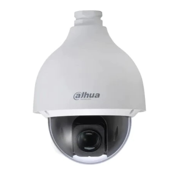
CAMERA SELECTION OTDAU software requires one camera, and optionally two, to detect and then track moving objects. It provides for two types of hardware and software interface to cameras: • USB webcams which may be external to your computer or built-in •... - Page 8 Dahua cameras tested and selected for UFODAS over competing brands and models due to: Best price vs performance Excellent light sensitivity and resolution Rugged enclosures and ability to maintain water-proof rating mounted dome-up 5-year warranty N53AB52 DH-IPC-EBW81242N 42212TNI 50232XANR 49425XBNR Image sensor 1/2.7-in 5MP...
-
Page 9: System Power Requirements And Sources
SYSTEM POWER REQUIREMENTS AND SOURCES UFODAP cameras and the Multi-Sensor Data Acquisition Unit (MSDAU) both use Power over Ethernet (PoE) as a power source as a path for the data to a computer or router. All six of the recommended cameras are PoE compatible meaning that a single Ethernet cable provides the communication signals as well as power over otherwise unused wire pairs. - Page 10 • 50230UNI-A 30x optical zoom camera – 23W max. • 42212TNI 12x optical zoom camera – 12W • NK8BR4 panoramic camera – 12W • N53AB52 bullet camera – 6W • MSDAU – 4W • PowerBeam Ethernet Bridge – 8.5W AC power for an Injector and possibly a computer may simply be from a wall-outlet in a fixed installation or from a portable source such as a DC-to-AC inverter powered by an automotive 12VDC source or from a solar/battery system.
-
Page 12: Dome Camera Preparation
DOME CAMERA PREPARATION Dahua dome cameras are provided with a lens cover and tape to protect the pan/tilt mechanism from damage during shipping. This must be removed prior to use. Remove the dome using the provided star wrench to unscrew the three screws that fasten the dome to the housing, as shown below. - Page 13 Remove the tape and lens cover and set aside for possible shipping, perhaps for warranty repair, should that be necessary. Replace the dome onto the camera, taking care that the o-ring is in place and tighten the three screws.
-
Page 14: Tripod Installations For Cameras
TRIPOD INSTALLATIONS FOR CAMERAS DAHUA 50230 OR 42212 CAMERA SETUP Your system may have one or more Dahua 50230 30x zoom or 42212 12x zoom cameras. If so, then perform the following steps. A Dahua 44212 camera mounted on a Camera Mount is shown below. Note that the tripod legs may be extended and spread from vertical to fully horizontal to accommodate a wide range of height and stability requirements. - Page 15 PoE power injector with power supply and line cord. Note: These cameras cannot be used with a POE164 Injector due to its lower, 30W output power. The POE164 may be used with the N53AB52 camera. 4. Ethernet 6’ cable 5. Ethernet 100’, 196’ or 300’ all-weather cables. Note: The maximum length for a camera to injector cable is 100 meters or 328 feet.
-
Page 16: Dahua N53Ab52 Camera Setup
DAHUA N53AB52 CAMERA SETUP If your system has one or more Dahua N53AB52 bullet or other fixed cameras perform the following steps. Collect the following components: 1. Dahua camera on junction box with tripod mount and Ethernet connector. 2. Standard camera tripod with 1/4-20 threaded mount 3. - Page 17 3. The initial height of the camera may be adjusted by spreading the tripod legs and by how far the legs are extended. To extend them, unlatch, extend/retract and re-latch. For stability, it is better to spread the legs to a wider rather than narrower stance and extend the legs if necessary to achieve a desired height.
-
Page 18: Fixed Camera Installation
FIXED CAMERA INSTALLATION POLE OR CORNER MOUNTING Installing a camera on a fixed structure such as a building or a tower requires consideration of how the camera will be attached to the structure and how its PoE connection will be made to assure a waterproof connection. Several junction boxes and adapters are available from ufodap.com. - Page 19 NOTE: If pole/pipe mounting, the pipe should be rigidly attached and supported to the structure such that the camera and/or MSDAU do not move in windy conditions, as shown in the example below. The optional addition of the owl can sometimes be helpful to prevent birds from landing on the dome, leaving behind residue that can obscure the view.
- Page 20 Outdoor installations in environments known for potential lightening action should provide for proper surge suppression. One way to accomplish this is to use a good- quality surge suppressor near the MSDAU/Camera and another at the entrance to the structure where the Ethernet cable will attach to the router. One such suppressor is shown below.
-
Page 21: Wall Mounting
Any UFODAP camera may be provided with a junction box and mounting accessories to allow it to be mounted to a vertical wall. The following steps are an example of how to mount and cable an N53AB52 fixed optics camera to a wall if no junction box-mounted Ethernet connector is provided. - Page 22 3. Unscrew and remove the outer gland nut shroud and insert the end of the camera cable that has no boot through the shroud and the nut into the box, as shown below. 4. Plug the cable into the camera’s Ethernet jack and dress the cables inside the box as shown:...
- Page 23 5. Reinstall the shroud to the nut and tighten the shroud by hand as much as possible. Be sure that the rubber gasket under the shroud has fully tightened against the cable.
- Page 24 6. Reinstall the camera mounting plate to the box using the three screws previously removed. Be sure that the orientation of the camera is as shown below so that it can be tilted up. Note that when positioning the camera field of view, it may be both rotated and angled. Loosen the Philips screw on the side of the camera mount.
-
Page 25: Msdau Installation
MSDAU INSTALLATION The MSDAU is designed for three methods for mounting – tripod, wall corner or pole. An MSDAU and the passive Camera Mount share a common System Mounting Assembly. The System Mounting Assembly consists of two black plates attached to each other at a right angle. - Page 26 A tripod mounted MSDAU with Dahua 42212 camera and Camera Junction Box is shown below. Any camera and the MSDAU are powered via their own Ethernet cable to PoE injector. In the above configuration, the camera and the MSDAU each require an Ethernet cable to an injector, usually located near a router.
- Page 27 For pole or corner mounting, the MSDAU is provided with the System Mount backplate and the pole mount option, shown below. Three stainless steel straps are provided to attach the pole mount to any vertical, rigid pipe. Be sure that the pipe is sufficiently supported so that, with the weight of the MSDAU, it does not move in the wind.
-
Page 28: Msdau Rf Antenna
MSDAU RF ANTENNA The MSDAU provides a standard SO-239 connector on the right side for an external antenna connection, as shown below with the included cable and connectors for the antenna mount. The design of the antenna used will determine its optimum gain and frequency range. - Page 29 A telescoping antenna, as shown below, may be directly connected to the antenna mount via a PL-259 to SMA adapter, included with the antenna. This is typically a ¼ wave whip which is omnidirectional but has no well-defined ground plane. Its gain at any particular frequency is dependent on its extended length. The optimal values may be calculated using this Whip Antenna Length and Frequency Calculator: http://www.csgnetwork.com/antennagenericfreqlencalc.html...
- Page 30 An Ultra-Wide-Band (UWB) type antenna can provide higher gain throughout a broader spectrum of frequencies such as 1MHz to 6GHz in the case of the example below. The various length elements are the primary antenna. Its response is omnidirectional, primarily in the horizontal plane. Such an external antenna would be connected directly to the MSDAU antenna connector, shown above.
-
Page 31: Pole-Mounted Camera Installation
POLE-MOUNTED CAMERA INSTALLATION A pole-mounted camera utilizes a junction box between the camera mount and the pole mount adapter, as shown below. The junction box provides a waterproof transition from the camera’s Ethernet connector to a box-mounted connector you use to attach the Ethernet cable. -
Page 32: Preparing A Dome Camera For Operation
PREPARING A DOME CAMERA FOR OPERATION The Dahua 50230 and 42212 PTZ cameras are shipped with a protective cap over the internal lens, taped to the sides of the pan-tilt mechanism. This cap must be removed prior to use. 1. Locate the L-shaped star wrench tool provided with the camera. 2. - Page 33 6. Place the dome back on the camera body, locating the three screws into the three sockets, making sure that the o-ring is in place. 7. Use the star tool to tighten the three screws. 8. Verify that the camera dome is dust-free. If it is dirty, clean it with a slightly damp, soft cloth.
-
Page 34: Ethernet Cable Connections
ETHERNET CABLE CONNECTIONS 1. Connect the waterproof Ethernet cable to the connector on the mounting box as shown below. To do this, start with all parts of the connector housing unscrewed. Plug the Ethernet cable connector into the box connector until the latch snaps in. Move the larger connector housing toward the connector and screw it all the way onto the box connector. - Page 35 installation is not in the US, just use an AC adapter or a different line cord in accordance with your AC power wall socket. 3. Using a second, short Ethernet cable, plug one end into the LAN connector on your PoE injector. For a 4-port injector, this is the right connector on the front of the PoE injector labeled “5 - Uplink”.
- Page 36 If the injector can be located near the router, then plug the other end of the short Ethernet cable into an unused router port. If the camera and injector will be used in a location remote from the router and AC power is available at that location, then a WiFi Extender that includes a wired Ethernet port may be used to provide a wireless connection from the injector to the router.
- Page 37 8. If the camera will only be used by a computer directly connected to the router, either by an Ethernet cable or by WiFi, the software will address the camera by its native IP address and port number. For example: 192.168.1.108 is the standard initial IP address for all Dahua cameras.
-
Page 38: Setting Up An Installed Camera
SETTING UP AN INSTALLED CAMERA Perform the following steps before you mount the camera at its permanent, perhaps inaccessible location. Before attempting to use the camera with operational software such as OTDAU, it is wise to verify that it and the injector/router are all operating correctly. This can be accomplished by using either: •... - Page 39 3. When you run it, it discovers and displays all Dahua IP cameras on your LAN. You can then modify the IP address if necessary. 4. Click on the WEB symbol on the right to run Internet Explorer to access the camera’s Settings options.
- Page 40 Click on the Setting tab to access all of the camera’s adjustments, as referenced below.
- Page 41 All necessary settings have already been adjusted prior to delivery of your system. If you change any of the Network settings, then the default configurations provided with OTDAU and Mission Control software will not work and would have to also be adjusted to match. In case you need to check or redo them, they are the factory defaults except as follows: The following section illustrates how to change these settings.
-
Page 42: Dahua Camera Configuration
DAHUA CAMERA CONFIGURATION When you purchase a camera from UFODAP, all the following settings have already been implemented when the camera was tested, prior to shipment to you. The username and password were also set to match the sample configurations included with OTDAU software. - Page 43 Set Picture settings to Profile Normal and leave others as shown above. Set Flip to 180 degrees. Set Exposure settings as shown above.
- Page 44 Set Backlight Profile to Normal and Mode Off. Set WB to Profile Normal and Mode Auto.
- Page 45 Set Day & Night settings as shown above. Set Focus & Zoom settings as shown above.
- Page 46 Set Defog Profile to Normal and Mode to Auto.
- Page 47 Disable all OSD info options. Above shows frame resolution for 704 x 480, 20 frames per second. 1280 x 720 or 1920 x 1080 at up to 30 FPS could also be selected depending on OTDAU computer capacity. ONVIF Authentication should be set to Off for no authentication.
- Page 48 Set a Static IP address as desired. Leave the other setting as is. 192.168.1.108 is the Dahua standard default address. You can leave this as is if it does not conflict with another device address. NOTE: If you have difficulty connecting to the camera or it seems intermittent, then you may have an address conflict.
- Page 49 of digits is the device’s unique address, such as 108. If your camera and router are not on the same LAN, then correct that by changing the IP address of the router or that of the camera, as shown below. It may be easier to change the router if all your other devices use DHCP addressing (not static).
- Page 50 Select a HTTP Port number other than the default of 80 if the camera is needs to be port-forwarded on your router. Leave it as 80 otherwise.
- Page 51 SETUP FOR OPERATION WITHOUT A ROUTER You can setup an OTDAU/MC system where the camera(s) connect directly to a computer, without going through a router. This configuration may be required, for instance, when setting up a system that has to operate stand-alone, independent of any direct internet connection.
- Page 52 Press the Windows + R keyboard shortcut to bring out the Run box. Enter “ncpa.cpl” and open the “Network Connections” window. Right-click your computer’s network adapter and select “Properties”.
- Page 53 Select your computer’s Internet Protocol Version 4 and click “Properties”. 5) Select “Use the following IP address” and change the IP address to the desired IPv4 address such as 192.168.1.50 as shown in this example. NOTE: This address must match the one in the IP field of the OTDAU Configuration when using an instance of OTDAU with Mission Control software.
- Page 54 IMPORTANT -- Use whatever means are provided by your router to: Change the range of addresses that the router uses for DHCP so that DHCP will use IP addresses (192.168.1.xx) such that xx is always smaller than the highest DAU address. For example, set the DHCP address range to 10 to 100.
-
Page 55: Dual Camera Setup For Triangulation
DUAL CAMERA SETUP FOR TRIANGULATION Triangulation of a tracked object’s geolocation, altitude, speed and size requires two running copies of OTDAU, each with one or two cameras. Triangulation calculations and display is performed by the Mission Control (MC) software. MC derives the data it needs to do that by communicating with two OTDAUs via the LAN or WAN. -
Page 56: Camera Separation For Triangulation
CAMERA SEPARATION FOR TRIANGULATION... -
Page 57: Maximum Target Detection Distance
MAXIMUM TARGET DETECTION DISTANCE In general, the maximum altitude that a UFODAP camera might see a target would not depend on the absolute altitude, per se, but rather the size, brightness and contrast of the target. "Seeing" might be defined as the target just covering enough pixels, with enough brightness so that the tracking settings of the OTDAU software detect it. -
Page 58: Camera Calibration For Triangulation
CAMERA CALIBRATION FOR TRIANGULATION For MC to calculate the location, altitude, etc. of a triangulated target from the position of a target in the FOV of two cameras, the pan and tilt (azimuth and elevation) angles of each of the two cameras must be setup in advance. The setup assumes that each of two instances of OTDAU software is controlling one PTZ camera. -
Page 59: Tips And Techniques
TIPS AND TECHNIQUES The following are some guidelines for common problems and questions UFODAP users have had while setting up or using UFODAP hardware or software or planning for a new system. TELESCOPE CONTROL It should be possible to control a GoTo telescope via the OTDAU software. However, the software interface (driver) to do that has not been developed. -
Page 60: Camera Separation For Triangulation
Its data sheet and dimensions may be found in the Downloads section of ufodap.com. This antenna is mounted to a standard NMO (New Motorola) adapter attached to an assembly that fastens to the vertical plate that holds the MSDAU, high enough to clear the camera. -
Page 61: Msdau Mounting On A Vehicle
CPU resources. If your field of view is limited to less than a fixed camera, such as the N53AB52 with an FOV of 98 degrees and max resolution of 2592x1944, then that may be good enough and cost less. -
Page 62: Tracking Problems
One possible error message you may encounter while installing UFODAP software may be from the software installer noticing a very low amount of system RAM you have, e.g., 2GB. The UFODAP User Guide specifies a minimum system of: • Windows 10 OS on a PC Computer with Core i5 processor, 16GB memory and 2GB free disk memory. -
Page 63: Testing Otdau Setup And Tracking
Get into the camera's Setup menus via IE (easiest via Dahua's ConfigTool, found at the bottom of the home page of dahuawiki.com) Go to Focus and Zoom settings and set to Manual focus -- Any auto focus tends to lose tracking as it adjusts while tracking •... - Page 64 -- The predicted position is derived from measuring the vector velocity of a potential target during the number of frames specified by the Tracking, "Min events" parameter. After that number of detections are measured, it uses the estimated lag time of the software/camera to derive what the target location will be in the future and move to that point.
-
Page 65: System Setup For Triangulation
-- The configured FPS should match whatever the camera is set to, which has various options depending on resolution. If they don't match that will affect two things: Displayed frame rates will be inaccurate; The length of recordings will not match actual times. It should not affect tracking. -- Pan/Tilt values are actual when a camera is a PTZ type. -
Page 66: Initial Camera Connection And Testing
including an initial focus setting. You can review them using the Dahua software found at dahauwiki.com: "configtool". Use ConfigTool to test that your camera/injector/router is functioning properly. Use it to load IE to display the camera's web page by clicking on "web"... -
Page 67: Can A Camera Be Used With Other Software As Well As Otdau And Mc At The Same Time
-- Install ConfigTool from dahuawiki.com on your PC. Run it to verify that it detects your camera and shows it as IP address 192.168.1.108. -- One the line showing the camera in ConfigTool, start the IE browser via the "web" icon. - Page 68 Here is what you need to do to get the system installed (see also the System Installation Guide, downloadable from ufodap.com): -- Pry out and save the gold pin from the top of the antenna connector. Then you can screw the whip antenna adapter into the connector.
Need help?
Do you have a question about the N53AB52 and is the answer not in the manual?
Questions and answers