Table of Contents
Advertisement
Quick Links
Advertisement
Table of Contents

Related Manuals for OPTILAB BPR EVB

Summary of Contents for OPTILAB BPR EVB
- Page 1 BPR EVB User’s Manual Balanced Photo Receiver Evaluation Board Caution: The user must read this manual before operating the BPR EVB. Operations other than those described in this manual may result in personal injury and damage to the unit. Ver. 2.1...
- Page 2 Copyright © 2015 by Optilab, LLC. All rights reserved. This document is copyrighted property of Optilab, LLC. It may not be used in whole or in part for manufacture, sale, or design of items without the written permission of Optilab, LLC.
-
Page 3: Table Of Contents
BPR EVB User’s Manual Table of Contents BPR Configuration..........................1 Bandwidth Adjustment ......................2 Operation Mode ........................... 2 Evaluation Board ..........................3 Device Mounting Procedure ....................3 Schematic of Evaluation Board ..................... 4 Default Setting ..........................4 2.3.1 How to use manual gain control (MGC) mode ............. 5 2.3.2... -
Page 4: Bpr Evb User's Manual
BPR EVB User’s Manual 1 of 7 1. BPR Configuration 1.1 Butterfly Package Pin-out Diagram and Description BPR is packaged inside a 14-pin butterfly package. For your reference, we have included a table for the pin-out diagram for the BPR. -
Page 5: Bandwidth Adjustment
OA (Pin 4), 0 ~ 3.3 V Shut Down N.A. The default setting on the evaluation board is MGC. GC is preset to Vcc to maximize the TIA gain. Optilab, LLC 600 E. Camelback Road, Phoenix, AZ 85012 Phone: 1-888-553-3888, Fax: (602) 343-1489, Email: sales@oequest.com... -
Page 6: Evaluation Board
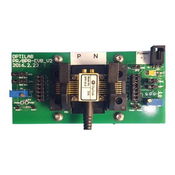
Mount BPR to Evaluation board using the four 2-56 screws provided. iii) 4x 2-25 Once secured clamp pins down in pin chuck, as shown in Fig. 2. screws Figure 2. BPR mounting procedure Optilab, LLC 600 E. Camelback Road, Phoenix, AZ 85012 Phone: 1-888-553-3888, Fax: (602) 343-1489, Email: sales@oequest.com... -
Page 7: Schematic Of Evaluation Board
The evaluation board has been preset to MGC mode with the highest bandwidth setting. Both PDs are reversed biased at Vcc. The TIA gain is maximized (GC = Vcc). Optilab, LLC 600 E. Camelback Road, Phoenix, AZ 85012 Phone: 1-888-553-3888, Fax: (602) 343-1489, Email: sales@oequest.com... -
Page 8: How To Use Manual Gain Control (Mgc) Mode
JP6 and JP8 are jumped on pin 1 and 2. Adjust the differential gain by adjusting the potentiometer GC (R1), clockwise to increase gain. MODE Figure 6. BPR-EVB in MGC Mode Optilab, LLC 600 E. Camelback Road, Phoenix, AZ 85012 Phone: 1-888-553-3888, Fax: (602) 343-1489, Email: sales@oequest.com... -
Page 9: How To Use Automatic Gain Control (Agc) Mode
To use AGC mode, ramp down DC power then turn off. Follow the instruction in section 2.3.2 to make proper jumpers then ramp up DC power to 3.3V. Optilab, LLC 600 E. Camelback Road, Phoenix, AZ 85012 Phone: 1-888-553-3888, Fax: (602) 343-1489, Email: sales@oequest.com...
Need help?
Do you have a question about the BPR EVB and is the answer not in the manual?
Questions and answers