Advertisement
Quick Links
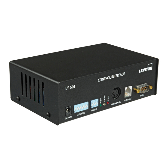
INTRODUCTION
The I/F 501 interface unit allows a variety of comunication protocals used in NSI and other industrial equipment
to be translated between one another. In addition the I/F 501 can serve as an independent, programmable lighting
controller. The I/F 501 also serves as the interface between NSI' s Luma-net network and a personal computer.
SPECIFICATIONS:
Microplex Input (I/O)
Microplex Ouput (I/O)
DMX 512 Input
DMX 512 Output
AMX 192 Output (optional, replaces 512)
RS-232 I/O
MIDI input / Analog input
Luma-net I/O
Power requirements
Although many different connectors are present on this unit, in most configurations, one or more of the connectors
may serve no function. It is important that the installer verify that the required inputs and outputs operated in the
mode required for the application. Please read the appropriate application sheets in this manual carefully before
installing.
INTERFACE UNIT
INSTALLATION AND OPERATION GUIDE
Software Revision 1.05, Version A
I/F 501
3 pin XLR male
3 pin XLR female
5 pin XLR male (USITT spec)
5 pin XLR female (USITT spec)
4 pin XLR female (USITT spec)
9 pin ' ' D' ' connector
5 pin din 180 degree connector
Modular style telephone connector
+15VDC 200ma (power supply included)
IMPORTANT
Advertisement

Subscribe to Our Youtube Channel
Summary of Contents for NSI I/F 501
- Page 1 INSTALLATION AND OPERATION GUIDE INTRODUCTION The I/F 501 interface unit allows a variety of comunication protocals used in NSI and other industrial equipment to be translated between one another. In addition the I/F 501 can serve as an independent, programmable lighting controller.
- Page 2 INTERFACE UNIT Software Revision 1.05, Version A Front Panel DC Power input - Connect 15VDC (+ tip, - ring) 250ma here. (Supplied with unit.) Address - Controls translation of adresses (and other special functions). See individual applications details. Config - Determines the operating mode of the unit. PWR - Indicates presence of +15VDC STAT - Usually indicates presence of input signal.
-
Page 3: Jumper Locations
INTERFACE UNIT Software Revision 1.05, Version A JUMPER LOCATIONS JUMPER LOCATIONS PCB locations of jumpers / internal connectors NSI CORPORATION... - Page 4 INTERFACE UNIT Software Revision 1.05, Version A I/F 501 JUMPER CHANGE QUICK REFERENCE CHART INPUT -> OUTPUT DEFAULT SETTINGS MPX -> DMX MPX -> AMX DMX -> MPX MIDI -> MPX/DMX MIDI -> AMX RS-232 -> MPX/DMX RS-232 -> AMX LUMANET/MPX/DMX ->...
- Page 5 INTERFACE UNIT Software Revision 1.05, Version A PINOUTS PINOUTS Pinouts of the various connectors NSI CORPORATION...
- Page 6 INTERFACE UNIT Software Revision 1.05, Version A MICROPLEX TO DMX 512 In this application, Microplex is converted to DMX-512. The Microplex is then retransmitted. P4 & 5 JP6 & 7 OPEN CLOSED DIPSWITCH POSITIONS CONNECTOR Microplex IN Microplex OUT DMX IN DMX out MIDI / Analog Luma-net...
- Page 7 INTERFACE UNIT Software Revision 1.05, Version A MICROPLEX TO AMX 192 In this application, Microplex is converted to AMX-192. The 5 pin XLR may be replaced with a 4 pin XLR (USITT) if desired. P4 & 5 JP6 & 7 OPEN OPEN CONNECTOR...
- Page 8 INTERFACE UNIT Software Revision 1.05, Version A DMX 512 TO MICROPLEX In this application, DMX 512 is converted to Microplex.. P4 & 5 JP6 & 7 CLOSED CLOSED *CLOSE TO TERM STARTING DMX CHANNEL FOR MICROPLEX BY 16 INCR. DN:64 CONNECTOR Microplex IN Microplex OUT...
- Page 9 INTERFACE UNIT Software Revision 1.05, Version A MIDI TO MICROPLEX and DMX 512 In this application, MIDI note commands are converted to Microplex and DMX 512 dimmer levels. P4 & 5 JP6 & 7 OPEN CLOSED A1-4 SELECTS MIDI CHAN, 5 UP SETS IGNORE NTOFF CONNECTOR Microplex IN Microplex OUT...
- Page 10 INTERFACE UNIT Software Revision 1.05, Version A MIDI TO AMX-192 In this application, MIDI is converted to AMX 192. P4 & 5 JP6 & 7 OPEN OPEN A1-4 SELECTS MIDI CHAN, A5 UP SETS IGNORE NTOFF CONNECTOR Microplex IN Microplex OUT DMX IN *DMX out MIDI / Analog...
- Page 11 INTERFACE UNIT Software Revision 1.05, Version A RS-232 to MICROPLEX and DMX 512 In this application, a computer may send simple ASCII commands to operate individual dimmer channels. P4 & 5 JP6 & 7 OPEN CLOSED CONNECTOR Microplex IN Microplex OUT DMX IN DMX out MIDI / Analog...
-
Page 12: Operation
INTERFACE UNIT Software Revision 1.05, Version A RS-232 TO AMX 192 In this application, a personal computer may send ascii commands to operate individual dimmer channels. P4 & 5 JP6 & 7 OPEN OPEN CONNECTOR Microplex IN Microplex OUT DMX IN *DMX out MIDI / Analog Luma-net... - Page 13 INTERFACE UNIT Software Revision 1.05, Version A LUMA-NET to MICROPLEX In this application, Microplex or DMX is mixed with LUMA-NET and transmitted as Microplex. P4 & 5 JP6 & 7 CLOSED CLOSED *CLOSE TO TERM CLOSE TO TERM CONNECTOR Microplex IN Microplex OUT DMX IN DMX out...
- Page 14 INTERFACE UNIT Software Revision 1.05, Version A LUMA-NET to DMX-512 In this application, Microplex or DMX is mixed with LUMA-NET and transmitted as DMX 512. P4 & 5 JP6 & 7 OPEN CLOSE CLOSE TO TERM CONNECTOR Microplex IN Microplex OUT DMX IN DMX out MIDI / Analog...
- Page 15 INTERFACE UNIT Software Revision 1.05, Version A LUMA-NET to AMX - 192 In this application, Microplex or DMX is mixed with LUMA-NET and transmitted as AMX-192. P4 & 5 JP6 & 7 OPEN OPEN CLOSE CLS TO TERM LUMA CONNECTOR Microplex IN Microplex OUT DMX IN...
- Page 16 INTERFACE UNIT Software Revision 1.05, Version A ANALOG TO / MERGED WITH DMX 512 and MICROPLEX In this application, 0 to 10VDC is converted to Microplex or and DMX 512.. P4 & 5 JP6 & 7 OPEN CLOSED *CLOSE TO TERM STARTING ADDR OF ANALOG CHAN 1 BY 1 INCREMENT DN:64 CONNECTOR Microplex IN...
- Page 17 INTERFACE UNIT Software Revision 1.05, Version A ANALOG TO AMX-192 In this application, 0 - 10VDC is converted to AMX 192. P4 & 5 JP6 & 7 OPEN OPEN *CLOSE TO TERM STARTING ADDR OF ANALOG CHAN 1 BY 1 INCREMENT CONNECTOR Microplex IN Microplex OUT...
- Page 18 INTERFACE UNIT Software Revision 1.05, Version A AUTOCHASE TO MICROPLEX AND DMX 512. In this application, the unit serves as a stand alone chaser. P4 & 5 JP6 & 7 CLOSED CONNECTOR Microplex IN Microplex OUT DMX IN DMX out MIDI / Analog Luma-net RS-232...
- Page 19 INTERFACE UNIT Software Revision 1.05, Version A RS-232 AUTO-CUEING TO MICROPLEX AND DMX. In this application, the unit serves as a stand alone programmable memory lighting controller with precise timed crossfading. Optionally contact closures serve for manual control. P4 & 5 JP6 &...
- Page 20 INTERFACE UNIT Software Revision 1.05, Version A LUMA-NET 404CP EMULATION WITH EXTERNAL CONTACTS. In this application, the unit serves as a 404CP panel with external contact closures. P4 & 5 JP6 & 7 OPEN CLS TO TERM LUMA CONNECTOR Microplex IN Microplex OUT DMX IN DMX out...
- Page 21 INTERFACE UNIT Software Revision 1.05, Version A LUMA-NET SOFTWARE INTERFACE. This application is for use with the Luma-net Computer Software. This unit serves as the interface between the computer and the network. P4 & 5 JP6 & 7 OPEN CLS TO TERM LUMA CONNECTOR Microplex IN Microplex OUT...
- Page 22 INTERFACE UNIT Software Revision 1.05, Version A Lumanet Channel number codes / dipswitch settings. Multiply channel listed by increment required. Subtract one for Luma-net network ID no. 0 - switch down, 1 - switch up. Lumanet Dipswitch Lumanet Channel 1234567 Channel 0000000 1000000...
- Page 23 INTERFACE UNIT Software Revision 1.05, Version A DMX 512 Channel number codes / dipswitch settings. 0 - switch down, 1 - switch up 1st DMX Dipswitch 1st DMX Channel 1234567 Channel 0000000 1000000 0100000 1100000 0010000 1010000 0110000 1110000 NSI CORPORATION DMX 512 Channel number codes / dipswitch settings.
- Page 24 INTERFACE UNIT Software Revision 1.05, Version A ASCII Cues Implementation ASCII Cues Implementation Overview Following are the rules for editing ASCII Cues as implemented on the IF501, software revision 1.00: If you use a word processor for editing ASCII Cues you must set WORD WRAP OFF and the margin should be set to 80 characters per line.
- Page 25 INTERFACE UNIT Software Revision 1.05, Version A Keywords Supported. DOWN This keyword specifies the fade down time of the previous cue. This keyword must be followed by a space and the time in the range of ‘ ‘ 0" to ’ ’ 9:59.9". Minutes are optional but must be followed by a colon. In the absence of minutes, seconds may be specified up to ‘...
-
Page 26: Warranty
INTERFACE UNIT Software Revision 1.05, Version A NSI Corporation Limited Warranty WARRANTY NSI Corporation Limited Warranty NSI Corporation warrants new electronics products to be free from defective materials and workmanship for a period of one (1) year from the date of purchase to the original owner when purchased from an authorized NSI dealer.
Need help?
Do you have a question about the I/F 501 and is the answer not in the manual?
Questions and answers