Table of Contents
Advertisement
Quick Links
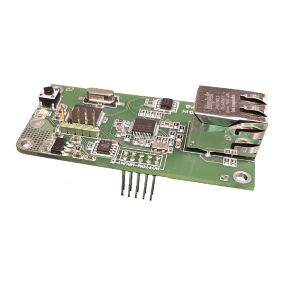
IOMB-TCP/IP INSTALLATION INSTRUCTION
ENGLISH
GATEWAY FOR I/O-MODULES. Fits IOMB-
02, IOMB-03 and IOMB-04.
TECHNICAL DATA
Supply voltage:
From the I/O-
modules IOMB-02
IOMB-03/IOMB-04
Communication:
TCP/IP
Connection:
RJ45
Indications LED on PCB
- Yellow, flash:
TCP/IP
communication
- Yellow, double flash: DHCP energising
via push button
- Green, fixed:
Operation
- Green, blink:
Internal Modbus
communication
Ambient temperature:
-20 till +50°C
Dimensions (WxHxD):
75x39x33 mm
USE
IOMB-TCP/IP is a gateway for IOMB-02, IOMB-
03 and IOMB-04 that permits communication
with the I/O modules via TCP/IP.
FUNCTION
The TCP/IP gateway communicates inter-
nally with the I/O module via modbus RTU and
externally via TCP/IP. In order for the factory-
set Modbus communication to work, all DIP
switches On the I/O module must be set to
OFF. You can change the Modbus communica-
tion settings in the web interface for the TCP/
IP gateway, in which case you must also adjust
the DIP switch settings in the I/O module.
The TCP/IP gateway has the capacity to com-
municate with one external device (e.g. OPC
server) at a time.
Calectro AB Phone: +46 31-69 53 00 info@calectro.com www.calectro.com
MOUNTING
The IOMB-TCP/IP is mounted using the 4 screws
and washers provided, onto the I/O modules IOMB-
02, IOMB-03 or IOMB-04.
By replacing the rubber gasket in the M20 screw in
the I / O module with the supplied multi-hole gasket,
a pre-contacted Cat5 / 6 can be used. See Figure 1.
Remove the termination jumper located on the I / O
module. Please note that the 10-pin strip fits correct-
ly during the assembling. See Figure 2.
INSTALLATION
The DIP switches (1–10) in the I/O module must be
in their OFF positions to enable internal communica-
tion between the I/O module and the TCP/IP gateway.
Instruction, connection to network:
1. Connect the TCP/IP module to the designated
location on IOMB-02, IOMB-03 or IOMB-04.
2. Fit the 4 accompanying washers and screws.
3. Energise the I/O module. The green and yellow
LEDs on the TCP/IP module light up.
4. Press the button to the right of the yellow LED and
hold it down until the yellow LED flashes twice.
The TCP/IP gateway is now set to receive an IP
address via DHCP.
5. Plug in the network cable.
6. To access the network settings, open a web
browser and search for host name: "http://calec-
trobrige". If you experience problems locating the
TCP/IP gateway, download and install the pro-
gram: "Microchip TCPIP Discoverer" available-
from Calectro's website: http://www.calectro.se/
products/#!/programvaror/. This program looks
for all connected gateways that have a TCP/IP
circuit from Microchip and displays their assigned
IP addresses.
7. Log in to network settings with the user name:
"admin" and password: "admin".
8. Click NETWORK SETTINGS to access the net-
work settings.
9. Under MODBUS SETTINGS you can manage
internal communication between the I/O module
and the TCP/IP gateway. You do not usually need
to adjust this. The default settings in MODBUS
SETTINGS correspond to the I/O module's DIP
switch in the OFF position.
MAINTENANCE
IOMB-TCP/IP is maintenance-free.
EN
MODBUS-SETTINGS FOR I/O-MODUL
(DIP-SWITCH: 0 = OFF / 1 = ON)
Modbus ID
DIP-switch
1,2,3,4,5 and 6
1
000000
2
100000
3
010000
4
110000
5
001000
6
101000
7
011000
8
111000
9
000100
10
100100
11
010100
12
110100
13
001100
14
101100
15
011100
16
111100
17
000010
18
100010
...
...
64
111111
Modbus Parity
DIP-switch 7 and 8
None (2 stop bits)
00
None (1 stop bit)
11
Even (1 stop bit)
10
Odd (1 stop bit)
01
Modbus Baud rate
DIP-switch 9 and 10
9600
00
19200
10
38400
01
57600
11
Reservation for changes and printing errors.
Advertisement
Table of Contents

Summary of Contents for CALECTRO IOMB-TCP/IP
- Page 1 IOMB-TCP/IP INSTALLATION INSTRUCTION MOUNTING MODBUS-SETTINGS FOR I/O-MODUL The IOMB-TCP/IP is mounted using the 4 screws (DIP-SWITCH: 0 = OFF / 1 = ON) and washers provided, onto the I/O modules IOMB- 02, IOMB-03 or IOMB-04. Modbus ID DIP-switch By replacing the rubber gasket in the M20 screw in...
- Page 2 MODBUS REGISTER FOR IOMB-02 Coils (0x) Function Range 4x0021 Digital output #1 default value 0 or 1 0x0001 Digital output #1 Off or On 4x0022 Digital output #2 default value 0 or 1 0x0002 Digital output #2 Off or On 4x0023 Analog output #1 default value 0 to 1000...
- Page 3 MODBUS REGISTER FOR IOMB-03 Coils (0x) Function Range 4x0024 Analog output #3 default 0 to 1000 value X100 (Volt) 0x0001 Digital output #1 Off or On 4x0025 Timeout for activating default 0-600 sec 0x0002 Digital output #2 Off or On values (4x0019-4x0024) 0x0003 Digital output #3...
- Page 4 FIG. 5 FIGURES FIG. 1 FIG. 2 Termination-jumper 10-pin strip FIG. 3 FIG. 6 FIG. 4 Calectro AB Phone: +46 31-69 53 00 info@calectro.com www.calectro.com...
Need help?
Do you have a question about the IOMB-TCP/IP and is the answer not in the manual?
Questions and answers