
Summary of Contents for Schlumberger CAMERON LEDEEN VA Series
- Page 1 ® CAMERON LEDEEN Quarter Turn Actuator VA Series – Pneumatic Installation, Operation and Maintenance Manual 05/02/2018 Initial release Garberi M. Cerati S. DATE ISSUE PREPARED BY APPROVED BY...
- Page 2 All the information contained in this manual is the exclusive property of Cameron. Any reproduction or use of the calculations, drawings, photographs, procedures or instructions, either expressed or implied, is forbidden without the written permission of Cameron or its authorized agent. Release – March 2018 © 2018 Cameron, a Schlumberger Company...
- Page 3 File copies of this manual are maintained. Revisions and/or additions will be made as deemed necessary by Cameron. The drawings in this book are not drawn to scale, but the dimensions shown are accurate. This book covers Cameron products. Cameron, a Schlumberger Company Ledeen Facility Via L. Gandini 4 27058 Voghera (PV) –...
- Page 4 NOTES:...
-
Page 5: Table Of Contents
CONTENTS GENERAL .......................................5 Legend for Safety Symbols ...............................5 Original Spare Parts ..................................6 Operative Staff ..................................6 Damages Derived From Use ..............................6 Interruptions and suspending ..............................6 Modification of The Actuator ..............................6 Actuator Disposal ..................................6 Safety of the Power Supply Connection (If Applicable) ......................7 Safety Recommendations .................................7 Electrostatic Discharges Prevention ............................7 Actuator Marking (According to 2014/34/EU Directive) ......................8... -
Page 6: General
I. GENERAL • Keep this manual for future reference. • Please keep this manual near the actuator so that it is available for consultation. • For questions or clarifications please contact cameron.slb.com • To get / request new copies of the manual please contact cameron.slb.com •... -
Page 7: Original Spare Parts
B. Original Spare Parts The use of any non-genuine Cameron spare parts by customer exempts Cameron from any responsibility for indemnity on claims. C. Operative Staff The maintenance-staff assigned to Cameron's Ledeen products must have the qualified technical preparation to perform the function. The lack of the above-mentioned preparation, included therein the unavailability to attend adequate training courses by specialized Cameron technicians at its workshop, cannot be charged to the company Cameron, who will be considered exempt from any responsibility on claims. -
Page 8: Safety Of The Power Supply Connection (If Applicable)
H. Safety of the Power Supply Connection (If Applicable) Before carrying out any operation on the actuator, check that the power supply is off. Before connecting the actuator: • Verify the absence of the power supply and always connect the ground cable to the actuator first. •... -
Page 9: Actuator Marking (According To 2014/34/Eu Directive)
K. Actuator Marking (According to 2014/34/EU Directive) Please refer to the following example of actuator marking: ε II 2 G c Tx Where: symbol of conformity to the EU applicable directives ε ATEX symbol group II (surface) apparatus of category 2 explosive atmosphere with presence of gas, vapours, fogs type of protection temperature class... -
Page 10: Actuator Name Plate Description
L. Actuator Name plate description The actuator nameplate shows the following data: 1. Contract No. 2. Purchase Order No. 3. Customer item 4. Valve and Actuator Tag Number 5. Actuator S/N 6. Actuator model 7. Valve size and rating 8. Actuator supply pressure (*) 9. -
Page 11: Receiving,Storage And Handling
II. RECEIVING,STORAGE AND HANDLING A. Preliminary Verification Upon Receipt of Material Warning: At receipt of the material: 1. Check the completeness of the supply, by referring to the packing list; 2. Check the tag number, serial number and technical information in the nameplate with reference to the order acknowledgement. - Page 12 • To store the actuator at temperatures below of –30°C and up to +70°C, it is necessary to carry out additional checks and tests from time to time, depending on the ambient conditions. Preservation conditions The procedures that must be performed to the equipment during storage to assure proper operation of the equipment after installation are the following: •...
-
Page 13: Handling
C. Handling Proper Lifting, Weights and Dimensions, Fastener Torque Chart Warning: Important: These instructions refer to the lifting of the actuator only, not assembled on the valve. Do not attempt to lift the actuator-valve assembly by using the lifting points of the actuator: The lifting equipment consists on commercial chains and slings of adequate dimensions, according to the weight of the actuator. - Page 14 LIFTING DEVICES MAXIMUM WORKLOAD Chains...
- Page 15 LIFTING DEVICES MAXIMUM WORKLOAD Slings...
-
Page 18: Operation
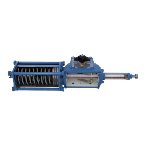
III. OPERATION This series pneumatic actuator is designed for on-off and control service and is applicable over a wide range of pressure, temperature and environments. The scotch yoke mechanism converts the linear motion of pneumatic piston into valve rotation by the actuator shaft. -
Page 19: Adjustment
e. Lift the actuator by means of adequate slings as per the weight of the actuator to render the perfect horizontal (this is very important for easy coupling) utilizing the existing lifting point on the actuator.( refer to pages no. 12-15) f. - Page 20 Figure 1 When the end cap seal need to be replaced (DA & SR) follow the instructions below:(see fig. 2) 1. Place the actuator in fail safe position. 2. Remove any electric power and pressure supply. 3. Unthread the lock nut (item 36) and the stop screw (item 35) paying attention to not remove completely the end stroke.
- Page 21 11. To reassemble the actuator, follow the disassembly in reverse order. 12. Once desired position is achieved, tighten the locking nut, applying 45-50Nm torque. Ensuring O-ring is properly centered on the stopper screw and fitted in the machined recess in the locking nut. 13.
- Page 22 b). Verification of Position Indicator Warning: Note: No special tools are required for these operations, but only some Allen wrenches and hexagonal wrenches of the required sizes. Position indicator alignment Verify the correct indication of the actuator position by the local position indicator: •...
-
Page 23: Actuator Start Up
C. Actuator Start up a. Arrangement for start-up Warning: Note: No special tools are required for these operations, but only some Allen wrenches and hexagonal wrenches of the required sizes . Pneumatic connections: a. Before connecting the actuator to the pneumatic supply line, check that pipes and fittings are according to the applicable plant specifications, in order to guarantee the required air flow for the operation of the actuator and to avoid that the supply pressure drops below the minimum allowable value. - Page 24 Check that the feed voltage values of the electric components (solenoid valves coils, micro switches, pressure switches etc., if applicable) are as prescribed. d) Check that the actuator controls, such as remote control, local control, emergency control etc. (if applicable), are properly working in accordance with the schematic diagram. e) Check that the required remote signals (valve position, air pressure, etc.) are correct.
-
Page 25: Maintenance
V. MAINTENANCE Every maintenance operation on the actuator must be carried out only after having closed the pressure taps in order to prevent undesired operation and enable the operating personnel to work in safe conditions. If present, shut-off the electric power supply and check the absence of hazardous atmosphere near the actuator. -
Page 26: Instruction For Replacement Of Dynamic Seals
Important: In case that the actuator or any of its part must be replaced, please follow the instructions of the “Actuator Disposal”. C. Instruction for replacement of Dynamic seals Warning: If there are leaks in the pneumatic cylinder or a malfunction in the mechanical components, or in case of scheduled preventative maintenance, the actuator must be disassembled and seals must be replaced with reference to the disassembly section (from page no. - Page 27 Figure 1 VA0 MODEL (HEAD FLANGE INTEGRATED WITH FRAME) Figure 2...
- Page 28 Replacement Piston rod seals : (See Figure 1 & 2) For replacing piston rod seal proceed as described here below: Warning: Remember that a preloaded spring is included in the cylinder. (If SR Actuator) • Slowly unthread the screws (item 45) of the tie rods (item 40) in the proper sequence, then remove the same screws with their washers (item 46).
-
Page 29: Trouble Shooting & Remedies
VI. TROUBLE SHOOTING & REMEDIES Problems Possible cause Remedy Lack of pneumatic supply Check supply line. Consult valve manufacturer Defective main valve documentation. Actuator doesn't work properly Failure of the control group Consult Cameron Ledeen. Actuator is incorrectly sized for torque Check the sizing criteria for both the Actuator output against the Valve torque. -
Page 30: Disassembly And Reassembly
VII. DISASSEMBLY AND REASSEMBLY Warning: Note: No special tools are required for these operations, but only some Allen wrenches, hexagonal wrenches of the required sizes, Torque wrench, Circlip plier, punch and nylon hammer. Note: If the RFID tag has been provided on the actuator that identifies each actuator with a unique number and when any disassembly process is undertaken, all components removed from within the actuator assembly must be reinstalled within that specific actuator during the reassembly process. - Page 31 Refer to the Spring return actuator assembly drawing below. ITEM DESCRIPTION FRAME SUB ASSEMBLY SPRING CONTAINER ASSEMBLY...
- Page 32 Refer to the Double acting actuator sectional assembly drawing below: ITEM DESCRIPTION ITEM DESCRIPTION ITEM DESCRIPTION SCREW GASKET SCREW SCREW COVER WASHER O-RING SCREW RIVET TIE ROD PISTON ROD FRAME COVER GUIDE SLIDER SOCKET HEAD SCREW NAME PLATE PISTON BUSHING HEAD FLANGE CYLINDER LINER SCREW...
- Page 33 Refer to the Spring return actuator sectional assembly drawing below: ITEM DESCRIPTION ITEM DESCRIPTION ITEM DESCRIPTION SCREW GASKET SCREW SCREW COVER WASHER O-RING SCREW RIVET TIE ROD PISTON ROD FRAME COVER GUIDE SLIDER SOCKET HEAD SCREW NAME PLATE PISTON BUSHING HEAD FLANGE CYLINDER LINER SCREW...
-
Page 34: Disassembly
A. Disassembly: Note: Before removing the actuator from the process piping for inspection by disassembly, check that the operating pressure is at atmospheric pressure. Also check that the pressure within the valve main unit is at atmospheric pressure to assure safety. Note: If the control valve is intended for the control of fluid containing drastic chemicals that are harmful to human body, be sure to check that the inside of the control valve is washed completely before starting the work. - Page 35 b. Disassembly of Cylinder sub assembly: (See the Exploded view below) (Refer pages 31 & 32 for sectional assembly drawings) ITEM DESCRIPTION ITEM DESCRIPTION 25** HEAD FLANGE SCREW O-RING SOCKET HEAD SCREW O-RING O-RING TIE ROD O-RING GUIDE SLIDER SCREW PISTON WASHER CYLINDER LINER...
- Page 36 Note: Before commencing any disassembly of the actuator, ensure that the actuator is isolated from the supply pressure and mechanical end stops are released. Note: Support the cylinder with proper lifting devices (Refer to page 12-15) for removing the cylinder assembly parts from frame.
- Page 37 c. Disassembly of Frame sub assembly: (See the Exploded view below) ITEM DESCRIPTION ITEM DESCRIPTION ITEM DESCRIPTION ITEM DESCRIPTION SCREW HOUSING O-RING BUSHING GASKET DRAIN PLUG FRAME PIN COVER SLIDING BLOCK SCREW O-RING SCREW WASHER CIRCLIP PISTON ROD FRAME COVER CIRCLIP (VA0 MODELS ONLY) SOCKET HEAD SCREW...
-
Page 38: Reassembly
1. Remove the Circlip (item 54) from the integrated head flange on frame ( If VA0 models ) 2. Remove the bushing (item 11) from the integrated head flange on frame ( If VA0 models ) 3. If desired, remove the external seal (item 39) and internal seal (item 26) from the integrated head flange (If VA0 models ) 4. - Page 39 3. Locate the scotch yoke (item 17) inside the frame and position it for accepting the shaft (item 48) perpendicularly through the bushing (item 16) of the frame. Ensuring that the shaft completely projects through the bushing (item 16) placed in the bottom side of the actuator frame. 4.
- Page 40 Note: If the actuator is VA0 model, the cylinder head flange (item 25) is integrated with frame. Place the frame assembly (item 10) on a suitable work bench in vertical orientation. Locate the head flange (item 25) external (item 39) and internal seals (item 26) and carefully place it in its grooves.
-
Page 41: Adjustment After Assembly
Assemble the gasket and frame cover in position by means of locating pins if any and fasteners (item 21 and item 22). Locate the position indicator assembly and install it in position of top of the frame in the same axis as that of the scotch yoke. -
Page 42: Spare Parts
VIII. SPARE PARTS 1. Frame sub Assembly (Refer to frame assembly exploded view on page 36) : • Item 19, qty. 1 • Item 47, qty. 2 • Item 48, qty. 2 • Item 51, qty. 1 2. Cylinder sub Assembly (Refer to pneumatic cylinder assembly exploded view on page 34) : •...
Need help?
Do you have a question about the CAMERON LEDEEN VA Series and is the answer not in the manual?
Questions and answers