Table of Contents
Advertisement
Quick Links
Advertisement
Table of Contents

Related Manuals for SPL IRON


Summary of Contents for SPL IRON
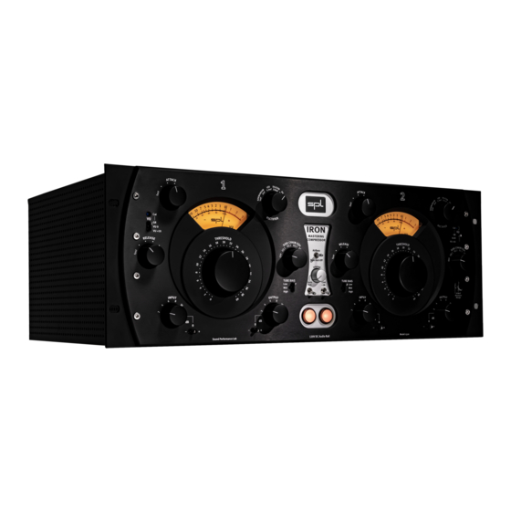
- Page 1 IRON Mastering Compressor Manual Version 2.0...
- Page 3 Index IRON Version 2.0 – 11/2022 Package Contents Introduction Operating Principles of a Compressor IRON Mastering Compressor Technical Aspects The 120V technology Innovating Compression Signal Flow Installation First Steps General Information Ground Lift switch to avoid ground loops Tube Warm-Up...
-
Page 4: Package Contents
This manual includes a description of the product but no guarantee as for specific charac- teristics or successful results. It describes the IRON Mastering Compressor in the hardware revision v2. IRON v2 differs from the first hardware version in the following details: 1. - Page 5 An authentic sound can only be achieved with the original unit. IRON Mastering Compressor The IRON mastering compressor is not a copy of a classic unit, but rather an original con- cept in itself. Our goal was to conceive a compressor that provided a pleasant, melod- ic-sounding, transparent compression, inspired on the vintage compressors of the radio era.
-
Page 6: Technical Aspects
Technical Aspects The 120V technology SPL‘s goal was to push analog signal processing to the limits. That‘s why we combined the best possible components with a high-grade optimized circuit design. The 120V technology is our reference technology. The 120V technology is unique in the world. - Page 7 All components in the audio device often operate at their limits. SPL devices with 120V technology can handle input levels of +32.5 dBu thanks to the higher internal operating voltage of +/- 60 volts – thus offering 12 dB more headroom.
- Page 8 It is not only crucial to use perfectly matched tubes – they also need to stay true to their specs as long as possible. Therefore IRON is equipped with matched 12AU7 tubes, which get paired with preselected matched pairs of Wathen CryoTone™12AX7- WCM Long Plate tubes at SPL.
-
Page 9: Signal Flow
Technical Aspects Signal Flow The following diagram depicts the signal flow within the IRON compressor. It is meant to clarify how it works and to show the relation between its different parameters. The audio signal flow is in blue and the control voltage signal flow is in green. -
Page 10: Installation
The IRON can be powered on and off with the use of a circuit breaker, as long as the total load does not exceed the rating of the latter. -
Page 11: General Information
General Information Ground Lift switch to avoid ground loops On the rear panel of the IRON mastering compressor (see details on page 13) is also a “GND LIFT” (Ground Lift) switch to avoid any ground loops. Ground loops take place when gear connected in the same network have different potentials. -
Page 12: Xlr Inputs And Outputs
This insert serves to connect an external external stereo equalizer into the side-chain of the IRON Mastering Compressor. This can be used to focus the response of the compres- sion to certain frequency ranges. This is also referred to as frequency selective compres- sion (for more information, see page 18). - Page 13 Selection: Remove Fuse Holder Change Fuses Flip Over Reinstall Fuses: V AC: T A L V AC: T A L IRON Serial Number XLRs: Balanced + dBu 1 = GND 2 = HOT (+) 3 = COLD (–) EXT SIDE CHAIN...
-
Page 14: Control Elements
Control Elements Control Elements IRON VU 0 mastering VU +10 compressor AirBass Tape Roll-Off TUBE BIAS TUBE BIAS Auto Link Byp. High High – – – VoltAIR Sound Performance Lab Model 1520 120V DC Audio Rail Input Output Threshold Tube Bias... - Page 15 Only signals that exceed the threshold level are compressed. Signals whose level is beneath the threshold value are not processed. The Threshold parameter of the IRON can be adjusted in 41 steps with the detent potentiometer. Do note, however, that the intensity of the compression depends also on the parameters Input, Tube Bias, Rectifier, Attack, Release and Side Chain EQs.
- Page 16 63% of its work. The Attack time can be adjusted in six steps, from Fast to Slow. The IRON does not offer the possibility to set an exact Attack time, since it is not a con- stant value and it depends on the rest of the parameters.
- Page 17 Control Elements Release The counterpart of the Attack is Release. The Release parameter determines how fast the compressor eases processing the signal. To be precise, it determines the time in which 63% of the reduced gain is restored. Similarly to the Attack time, the Release time can also be set in six steps from Fast to Slow.
- Page 18 This is also referred to as frequency selective compression. The side- chain filters are only in the control signal path – not in the audio path. The IRON Mas- tering Compressor offers a six-position switch to choose between the Off position, four side-chain filter presets or an external side-chain insert.
- Page 19 If no external equalizer is connected to the side-chain insert or if the send and return of the side-chain insert are not bridged with a cable, the audio signal in the IRON will be interrupted when the switch position (Ext) is selected.
-
Page 20: Auto Bypass
Compressors of this design do not have a fixed compression ratio. The lower the Threshold and the higher the input signal, the stronger the compression. This is actually one of the main factors that make the IRON‘s compression so musical. Auto Bypass... - Page 21 Control Elements Tape Roll-Off: This filter is based on the frequency response of tape machines. It can prove very useful to provide a nice rounding-off in the high end when the material being processed is too shrill. Tape Roll-o Bypass: In the following diagram you can see the frequency response curves for the AirBass and Tape Roll-Off presets, as well as that of the Bypass switch.
-
Page 22: Channel Switch
The CAL trimmer allows you to calibrate the display of the Gain Reduction on the VU meter. The IRON‘s Gain Reduction VU-meter ought to show 0dB after the warm-up phase. 0 dB on the VU meter correspond to an output level of 0 dBu. -
Page 23: Time Values
Time values Time values Time values depending on the rectifiers Although the Attack and Release times can be considered fixed intervals, the con- trol-time behavior and operating mode of the tubes is very different depending on the music. That is why these values should not be considered absolute values. The following chart should give an overview of the dependence of the control times of the input signal and the chosen Rectifier, with the same preset (OFF) of Side Chain EQ. -
Page 24: Specifications
Specifications Specifications Measurements Frequency Range (40 kHz = -3 dB) .....10 Hz- 40 kHz CMRR (at 0 dBu) ........1 kHz: › 80 dB / 10 kHz: › 65 dB THD & N (at 0 dBu) ........› 82 dB Noise (A-weighted) ........- 98 dBu Total Harmonic Distortion at -10 dBu: 0.3 % at 100 Hz, 0.06 % at 1 kHz, 0.02 % at 15 kHz at 0 dBu: 0.01 %... -
Page 25: Security Advices
Security Advices Security Advices Before starting up the device: • Read thoroughly and follow the security advices. • Read thoroughly and follow the this manual. • Observe all warning instructions on the device. • Please keep the user manual as well as the security advices in a safe place for future reference. - Page 26 Security Advices If you notice any abnormality When one of the following problems occur, immediately turn off the power switch and dis- connect the electric plug from the mains socket outlet. Then have the device inspected by a qualified professional. •...
- Page 27 SPL and the SPL Logo are registered trademarks of SPL electronics GmbH. SPL cannot be held responsible for damage caused by improper use or modification of the device or data that is lost or destroyed.
- Page 28 Security Advices...
- Page 30 © 2022 SPL electronics GmbH This document is the property of SPL and may not be copied or reproduced in any man- ner, in part or fully, without prior authorization by SPL. Sound Performance Lab (SPL) continuously strives to improve its products and reserves the right to modify the product described in this manual at any time without prior notice.
Need help?
Do you have a question about the IRON and is the answer not in the manual?
Questions and answers