Table of Contents
Advertisement
Quick Links
Advertisement
Table of Contents

Related Manuals for honle LED Cube 100

Summary of Contents for honle LED Cube 100
- Page 1 Operating Instructions LED Cube 100 # 69136a...
- Page 2 LED Cube 100 Masthead All rights reserved Copyright by Dr. Hönle AG Lochhamer Schlag 1, 82166 Gräfelfing / Munich Printed in Germany, Oktober 2013 These Operating Instructions and excerpts thereof must not be reprinted or reproduced in any other manner without the explicit written permission of Dr.
-
Page 3: Table Of Contents
Table of contents Warnings and symbols in these operating instructions ....... 4 1 Introduction ..................5 Usage ....................6 Areas of application ................6 2 Safety ....................7 General notes ..................7 Intended use ..................7 Safety of external components ............7 Thermal hazards ................. -
Page 4: Warnings And Symbols In These Operating Instructions
LED Cube 100 Warnings and symbols in these operating instructions You will find the following symbols next to all safety information/warnings in these Operating Instructions which indicate a danger to persons. An addi- tional signal word indicates the severity of any potential injury. -
Page 5: Introduction
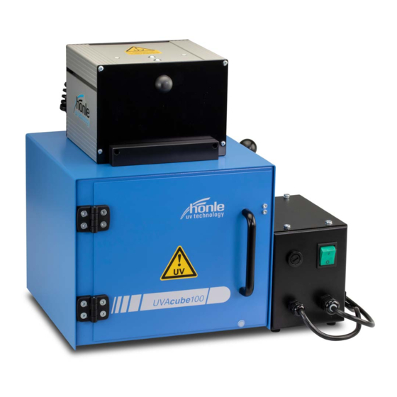
LED Cube 100 LED powerdrive Fig.1: LED Cube 100 with LED Spot 100 and LED powerdrive When the LED Spot 100 and the LED powerdrive control unit are operat- ed as an irradiation unit, the usage and safety instructions and the hazard... -
Page 6: Usage
The emission spectrum can be ad- Together with the LED emitter and justed to suit a huge range of ap- the control unit, the LED Cube 100 plications by using different LED forms a compact UV irradiation emitter components. The arrange-... -
Page 7: Safety
Safety of Safety of external components external The LED Spot 100 is placed on top of the LED Cube 100. The irradiation components chamber is connected to the LED powerdrive control unit. In addition to the usage information in these Operating Instructions, the safety information in... - Page 8 LED Cube 100 Fig. 3: LED Spot 100 Fig. 4: LED powerdrive control unit Safety: Safety: See LED Spot 100 See LED powerdrive Operating Instructions Operating Instructions The relevant safety and hazard information explains how to use the units safely and correctly. The Operating Instructions, especially the safety notes, must be observed by everyone that works with the unit.
-
Page 9: Thermal Hazards
Do not irradiate highly flammable or combustible substances in the ir- radiation chamber. WARNING! The interior of the LED Cube 100 and the units being ir- radiated can heat up during the process. Danger from Danger from gases... -
Page 10: Danger From Electrical Power
LED Cube 100 Danger from electrical power Danger from electrical The electrical equipment on all units must be checked regularly. power Inspection before starting work: Check all components of the unit for outwardly visible damage Check that all electric cables are in flawless condition Loose cable connections must be repaired immediately, and damaged ca- bles must be replaced. -
Page 11: Transport, Storage, Delivery
3 Transport, Storage, Delivery Scope of delivery: LED Cube 100 irradiation chamber 1. SUB-D 25-pin connection cable 2. Operating Instructions The following components are also required for irradiation: 1. LED unit (LED Spot 100) 2. Control unit (LED powerdrive) The delivered parts must be inspected for completeness and damage or other issues. -
Page 12: Startup And Operation
Mechanical Mechanical setup setup The LED Cube 100 is designed for mounting the LED Spot 100. The emit- ter is placed on top of the irradiation chamber. The irradiation chamber is then connected to the LED powerdrive control unit. TTENTION The LED Cube 100 may only be used with the LED Spot 100 and the LED powerdrive control unit. -
Page 13: Mounting The Led Spot 100
Fig. 5: Mounting the LED Spot 100 on the LED Cube 100 Connection to Connection to the LED powerdrive the LED The LED Cube 100 is connected to the LED powerdrive control unit via the powerdrive PLC interface, SUB-D 25: ... -
Page 14: Startup
The external safety shutdown on the PLC interface must be activated on ty shutdown the control unit when operating the LED Cube 100. To do this, set "ext. LEDenable" to "ON" in the Settings menu on the LED powerdrive: Set external safety shutdown... -
Page 15: Operation
Menu setting Value Display ext. LEDenable Fig. 7: Activating the external safety shutdown on the PLC interface Operation Operation 1. Open the door of the irradiation chamber. 2. Place the product in the irradiation chamber. 3. Close the door. 4. Start the irradiation procedure (see Operating Instructions: LED powerdrive): During the irradiation procedure, the blank plug on the bottom right- hand corner of the door lights up. -
Page 16: Measuring Intensity
2. Feed the UV-Meter cable through the opening in the housing 3. Place the surface sensor in the irradiation chamber Fig. 9: Routing the UV-Meter cable to the LED Cube 100 4. Close the door 5. Switch on the UV-Meter (see UV-Meter Operating Instructions) 6. -
Page 17: Service, Maintenance And Cleaning
No changes may be made to the LED Cube 100 and no fittings may be added or conversions performed without permission from Dr. Hönle AG. -
Page 18: Ordering Data For Units, Replacement Parts And Accessories
Article/Order number SUB-D 25-pin connection 66476 cable Operating Instructions 69136 WARNING! Only original replacement parts from Dr. Hönle AG may be used. Safe operation of the LED Cube 100 cannot be guaranteed if parts from other manufacturers are used. # 69136a... -
Page 19: Technical Data
PLC interface, SUB-D 25. Ambient Ambient conditions conditions The LED Cube 100 has been developed for use inside closed rooms or buildings with the following ambient conditions: Temperature +5°C to +35°C Max. rel. humidity...
Need help?
Do you have a question about the LED Cube 100 and is the answer not in the manual?
Questions and answers