Table of Contents
Advertisement
Quick Links
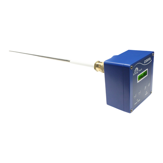
CODEL
Page 1
Operation and Maintenance
EnergyTech 301 Display Menu
Display Interface Manual
CODEL International Ltd.
Unit 4, Station Road, Bakewell, Derbyshire DE45 1GE United Kingdom
t : +44 (0) 1629 814 351
f : +44 (0) 8700 566 307
e : codel@codel.co.uk
web : www.codel.co.uk
Issue: A
Revision: 4
Date: 04/11/20
Ref:100255
Advertisement
Table of Contents

Related Manuals for CODEL EnergyTech 301


Summary of Contents for CODEL EnergyTech 301
- Page 1 CODEL Page 1 Operation and Maintenance EnergyTech 301 Display Menu Display Interface Manual CODEL International Ltd. Unit 4, Station Road, Bakewell, Derbyshire DE45 1GE United Kingdom t : +44 (0) 1629 814 351 f : +44 (0) 8700 566 307 e : codel@codel.co.uk...
- Page 2 CODEL Page 2 Operation and Maintenance Issue: A Revision: 4 Date: 03/11/20 Ref:100255...
- Page 3 CODEL Page 3 Operation and Maintenance Issue: A Revision: 4 Date: 03/11/20 Ref:100255...
-
Page 4: Table Of Contents
CODEL Page 4 Operation and Maintenance Contents Introduction ..........................1 Keypad Membrane ........................ 1 Welcome Screen ........................1 Menu structure ........................2 1.3.1 Main Menu ........................4 Measurements ........................4 1.4.1 Select Channel ....................... 4 Diagnostics ............................ 6 Running Mode ........................6 SIG Data .......................... - Page 5 CODEL Page 5 Operation and Maintenance 3.4.1 Damping Time ......................21 3.4.2 Stage 1 Gain ........................ 21 3.4.3 Stage 2 Gain ........................ 23 3.4.4 CF_m ........................... 23 3.4.5 CF_c ..........................24 3.4.6 Pressure ........................25 3.4.7 Temperature ....................... 26 3.4.8 Exit ..........................
- Page 6 CODEL Page 6 Operation and Maintenance Issue: A Revision: 4 Date: 03/11/20 Ref:100255...
- Page 7 CODEL Page 7 Operation and Maintenance Issue: A Revision: 4 Date: 03/11/20 Ref:100255...
- Page 8 CODEL Page 8 Operation and Maintenance Issue: A Revision: 4 Date: 03/11/20 Ref:100255...
-
Page 9: Introduction
To Scroll up/Increment To Scroll Down/Decrement 1.2 Welcome Screen The welcome screen displays Codel-FM (manufacturer’s name) and EnergyTech-300 Series (the device series name) The system will now enter initialising, this process will last 30 seconds. Few seconds later the measurement screen appears. -
Page 10: Menu Structure
Operation and Maintenance 1.3 Menu structure Below is a visual representation of the menu and submenu path system of an EnergyTech 301 that this document is based upon. Any further Submenus will be detailed later in the document. Main Menu... - Page 11 CODEL Page 3 Operation and Maintenance Main Menu Sum menu 1 Sub menu 2 Signal Damping Time Stage 1 Gain Stage 2 Gain CF_m CF_c Pressure Temperature Exit mA Outputs mA Output Unit Span Zero mA Simulation Exit Relay Output...
-
Page 12: Main Menu
CODEL Page 4 Operation and Maintenance 1.3.1 Main Menu The Instrument has following main menus. ➔ Measurements ➔ Diagnostics ➔ Setup Mode 1.4 Measurements This initial and default screen displays the measurement reading of the device. An overview of Measurements sub- menus is shown below. - Page 13 CODEL Page 5 Operation and Maintenance 1.4.1.1 mg/m3 Displays dust measurement in milligrams per cubic meter. to scroll through to mg/m3 and press to select mg/m3. The display returns to measurement screen displaying mg/m3 measurement. 1.4.1.2 mg/Nm3 Displays normalised dust measurement in milligrams per cubic meter.
-
Page 14: Diagnostics
CODEL Page 6 Operation and Maintenance 2 Diagnostics Allows user to view diagnostic data of instrument and are read only information. An overview of Parameters submenus is shown below. Main Menu Sum menu 1 Sub menu 2 Diagnostics Running Mode... -
Page 15: Sig Data
CODEL Page 7 Operation and Maintenance 2.2 SIG Data Allows user to access the diagnostic Signal Data at different amplification stages in circuit and it is read only information. The following are the submenus Main Menu Sum menu 1 Sub menu 2... - Page 16 CODEL Page 8 Operation and Maintenance 2.2.1.2 SIG Amplitude Displays analogue signal amplitude in millivolts before the signal digitisation. to scroll through to diagnostic Sig Data Submenu. 2.2.1.3 SIG Range Ratio Displays SIG Range Ratio which is ratio of signal amplitude to the total voltage range.
-
Page 17: Exit
CODEL Page 9 Operation and Maintenance 2.2.2 Exit Press to exit SIG diagnostic data submenu. 2.3 Status Mode Display the current system status and performance information for the device. Main Menu Sum menu 1 Sub menu 2 Diagnostics Device Status... - Page 18 CODEL Page 10 Operation and Maintenance • Device is in Power-Up condition • Device has no status flags set • Performance: • The Detector Retrieve value is below the threshold • The Detector Retrieve value is in saturation • The Detector Transmission value is below the threshold •...
-
Page 19: Exit
CODEL Page 11 Operation and Maintenance • Press to exit to Diagnostics submenu. 2.3.1 Exit Allows user to exit to main menu. • to scroll through to Exit and press to exit to main menu. Issue: A Revision: 4 Date: 03/11/20... -
Page 20: Setup Mode
CODEL Page 12 Operation and Maintenance 3 Setup Mode Setup Mode allows users to Setup instruments. An overview of Setup mode submenus are shown below. Main Menu Sum menu 1 Sub menu 2 Setup Mode Zero Calibration Span Calibration Parameters... -
Page 21: Full Zero Cal
CODEL Page 13 Operation and Maintenance 3.1.1 Full Zero Cal Allows user to activate Full Zero Cal. to scroll through to full Zero Cal. Press to activate Full Zero Cal. The Data valid light shall extinguish, and the user will be returned to the Zero Calibration Sub-Menu. If the user re- enters the menu “Wait for FZC”... -
Page 22: Fzc Frequency
CODEL Page 14 Operation and Maintenance 3.1.3.1 Set Full Zero Cal Allows users to setup time for Zero Calibration. Press to setup FZC Ref Time. to increment or decrement most significant digit on hours. Press to move cursor to next most significant digit, use to increment or decrement. -
Page 23: Exit
CODEL Page 15 Operation and Maintenance 3.1.5 Exit Allows user to exit to main menu. to scroll through to Exit and press to exit to Setup mode submenus. 3.2 Span Cal Allows user to activate Span calibration. The following are the submenus. -
Page 24: Insitu Span Cal
CODEL Page 16 Operation and Maintenance 3.2.1.1 Set Span Cal Target Allows users to set the span calibration target. Press to setup Span calibration target. The most significant digit is highlighted use to Increment or Decrement. Press to move cursor to next digit and finally press to exit Span Target Setup. -
Page 25: Exit
CODEL Page 17 Operation and Maintenance 3.2.3 Exit Allows user to exit to setup mode submenus. to scroll through to Exit and press to exit to Setup mode submenus. 3.3 Parameters Displays Communication parameters and Communication protocols. The following are the submenus. -
Page 26: Comms (B, D, P, S)
CODEL Page 18 Operation and Maintenance 3.3.1 Comms (B, D, P, S) Displays serial communication parameters and are read only. B is Baud Rate. D is Data Bits P is Parity S is Stop Bits to scroll through Serial Communication parameters. -
Page 27: Comms Address
CODEL Page 19 Operation and Maintenance 3.3.3 Comms Address Allows user to setup communication address of instrument. The following are the submenus. Comms Address. Set Comms Address. to scroll through Comms Address. 3.3.3.1 Set Comms Address Allows user to set communication address of instrument. -
Page 28: Running Mode
CODEL Page 20 Operation and Maintenance 3.3.4 Running Mode Allows the user to toggle between maintenance mode and normal running mode. to scroll through to Running Mode and press to enter the setup menu. to toggle between the maintenance option and the normal running option and press confirm the decision. -
Page 29: Signal
CODEL Page 21 Operation and Maintenance 3.4 Signal Allows the user to alter how the device handles the incoming and outgoing signals. Main Menu Sum menu 1 Sub menu 2 Setup Mode Signal Damping Time Stage 1 Gain Stage 2 Gain... - Page 30 CODEL Page 22 Operation and Maintenance Using the keys, the user can adjust the currently selected digit, ranging from 0 to 9. Exceeding this range automatically rolls the figure to the opposite end of the scale. By pressing the key, the current cursor moves to the next selectable digit.
-
Page 31: Stage 2 Gain
CODEL Page 23 Operation and Maintenance 3.4.3 Stage 2 Gain The stage 2 gain control allows the user to change the secondary gain. Press key to edit the Stage 2 Gain. to increase or decrease the gain (0-255). Press to enumerate through the menu and finalise the new Gain 2. -
Page 32: Cf_C
CODEL Page 24 Operation and Maintenance 3.4.5 CF_c To set up the offset factor, perform the following steps: Press key to set the CF_c Gain. Use the keys to increase or decrease the current digit between 0 – 9. By pressing the key, the current cursor moves to the next selectable digit. -
Page 33: Pressure
CODEL Page 25 Operation and Maintenance 3.4.6 Pressure To set up the pressure: Press key on the pressure screen to begin setting the pressure value. Use the keys to increase or decrease the current digit between 0 – 9. By pressing the key, the current cursor moves to the next selectable digit. -
Page 34: Temperature
CODEL Page 26 Operation and Maintenance 3.4.7 Temperature To set the temperature: Press key to set the temperature. Use the keys to increase or decrease the current digit between 0 – 9. By pressing the key, the current cursor moves to the next selectable digit. -
Page 35: Ma Output
CODEL Page 27 Operation and Maintenance 3.5 mA Output Allows user to setup mA output configuration. The following are the submenus. Main Menu Sum menu 1 Sub menu 2 Setup Mode mA Outputs mA Output Unit Span Zero mA Simulation Exit •... -
Page 36: Span
CODEL Page 28 Operation and Maintenance 3.5.2 Span Allows user to set up the span range. The following are the submenus. to scroll through to Span submenu. 3.5.2.1 Set Span Allows user to set span range. Press to access and set up span range sub menu. -
Page 37: Zero
CODEL Page 29 Operation and Maintenance 3.5.3 Zero Allows user to set up range for Zero mA. The following are the submenus. Zero Set Zero to scroll through to Zero submenu. 3.5.3.1 Set Zero Allows user to set range for Zero mA. -
Page 38: Simulation
CODEL Page 30 Operation and Maintenance 3.5.4 Simulation The simulation menu allows the user to simulate any mA output between 4-20 mA from the devices mA output. mA Simulation Set Output to scroll through the simulation menu options 3.5.5 Set Output... -
Page 39: Relay Output
CODEL Page 31 Operation and Maintenance 3.6 Relay Output Allows user to setup Relay output configuration. The following are the submenus. Main Menu Sum menu 1 Sub menu 2 Setup Mode Relay Output Rly Output Unit Direction Level Exit to scroll through to relay output submenu. -
Page 40: Direction
CODEL Page 32 Operation and Maintenance 3.6.1.1 Set Abs Location Allows users to set the absolute data location. Press to access and Set Abs Location. Use the keys to scroll through the available output units. Press to set the current output unit to the device. -
Page 41: Level
CODEL Page 33 Operation and Maintenance 3.6.2.1 Set Direction Allows users to set direction status of relay. Press to access Set direction sub menu. to scroll through different relay state options. press to set to the device. 3.6.3 Level Allows user to set up the alarm level. The following are the submenus. -
Page 42: Exit
CODEL Page 34 Operation and Maintenance • Press to move cursor to next most significant digit. Repeat above procedure to increment or decrement and finally press to set Span range and exit. 3.6.4 Exit Allows user to exit to setup mode submenus. -
Page 43: Time
CODEL Page 35 Operation and Maintenance 3.7.1 Time Allows user to setup clock. It has the following sub menu. Set Time. 3.7.1.1 Set Time Allows user to set time. • Use to scroll through to Time sub menu. • Press to access Set Time sub menu. -
Page 44: Date
CODEL Page 36 Operation and Maintenance 3.7.2 Date Allows user to setup date. It has the following sub menu. Set Date 3.7.2.1 Set Date Allows user to set date. • Use to scroll through to Date. • Press to access set date sub menu. -
Page 45: Eeprom
CODEL Page 37 Operation and Maintenance 3.8 EEPROM Allows user to read and write data into memory. The following are the sub menus. Main Menu Sum menu 1 Sub menu 2 Setup Mode EEPROM Read 0xXXXX Write 0xXXXX to 0xXXXX Exit •... -
Page 46: Write
CODEL Page 38 Operation and Maintenance • Press to move cursor to next most significant digit. Repeat above procedure to increment or decrement and finally press to set read memory location. 3.8.2 Write Allows user to write data into memory location. The following are the sub menus. -
Page 47: Exit
CODEL Page 39 Operation and Maintenance 3.8.3 Exit Allows user to exit to setup mode submenus. • Use to scroll through to Exit and press to exit to Setup mode submenus. 3.9 PassCode Allows user to assign a new PassCode for setup menu entry. -
Page 48: Set Read Address
CODEL Page 40 Operation and Maintenance 3.9.2 Set Read Address Allows user to enter memory location to read data. • Use to increment or decrement most significant digit in hexadecimal. • Press to move cursor to next most significant digit. Repeat above... -
Page 49: Exit
CODEL Page 41 Operation and Maintenance 3.9.4 Exit Allows user to exit to setup mode submenus. • Use to scroll through to Exit and press to exit to Setup mode submenus. Issue: A Revision: 4 Date: 03/11/20 Ref:100255...
Need help?
Do you have a question about the EnergyTech 301 and is the answer not in the manual?
Questions and answers