Table of Contents
Advertisement
Dec. 2009
Table of Contents
Cautionary Notes ..............................................................2
Specifications .....................................................................2
Location of Controls .........................................................3
Location of Controls Parts List........................................3
Exploded View ..................................................................4
Exploded View Parts List.................................................5
Parts List .............................................................................6
Verifying the Version Numbers......................................8
Data Backup and Restore Operations ............................8
Copyright © 2009 Roland Corporation
All rights reserved. No part of this publication may be reproduced in any form without the written permission
of Roland Corporation.
Performing a Factory Reset..............................................8
Updating the System ........................................................8
Test Mode ...........................................................................9
Board)................................................................................14
Circuit Diagram (Panel Board)......................................16
Board)................................................................................18
17058650E0
SERVICE NOTES
Issued by RJA
TU-3
CC-KWS
Advertisement
Table of Contents

Subscribe to Our Youtube Channel
Summary of Contents for Roland BOSS Chromatic Tuner TU-3
-
Page 1: Table Of Contents
Circuit Diagram (Analog, Input, Output, SW Verifying the Version Numbers........8 Board)................18 Data Backup and Restore Operations ......8 Copyright © 2009 Roland Corporation All rights reserved. No part of this publication may be reproduced in any form without the written permission of Roland Corporation. 17058650E0... -
Page 2: Cautionary Notes
• Because the part is made to order (at current market price). 2-7/8 (W) x 5-1/8 (D) x 2-3/8 (H) inches • Because it is carried in electronic data on the Roland web site. • Because it is a package or an accessory irrelevant to the function Weight maintenance of the main body. -
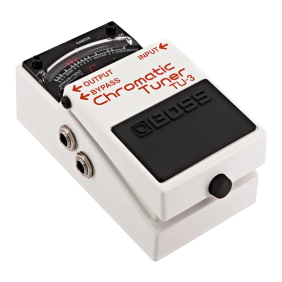
Page 3: Location Of Controls
Dec. 2009 TU-3 Location of Controls fig.Panel.eps Location of Controls Parts List Part Code Part Name Description Q’ty 5100008544 CASE 5100008548 DISPLAY COVER 5100009104 KPTL-3216SYCK 5100008546 ESCUTCHEON 5100006345 KCSA04-104 01903234 6.5MM JACK HTJ-064-13D 5100003918 JACK NUT M9X12X2 NI RTC(H5039510R0) 5100003926 WASHER 9X13.5X0.5T NI(H5039158R0) 5100001342... -
Page 4: Exploded View
Dec. 2009 TU-3 Exploded View fig.bunkaizu.eps 20-1 20-2 MAX2 MAX2... -
Page 5: Exploded View Parts List
Dec. 2009 TU-3 Exploded View Parts List Part Code Part Name Description Q’ty 5100008544 CASE 5100008545 PEDAL 5100008546 ESCUTCHEON 5100008547 HOLDER 5100008548 DISPLAY COVER 5100008549 SHIELD COVER 5100008238 PSA CAUTION (G2537401R0) 5100007504 COIL SPRING (22177109R0) 5100007505 PEDAL GUIDE BUSH (22157702R0) 5100008294 PEDAL PLATE (22357304R0) -
Page 6: Parts List
Dec. 2009 TU-3 Parts List fig.-part1-e.eps Due to one or more of the following reasons, SAFETY PRECAUTIONS: parts with parts code ******** cannot be supplied as service parts. The parts marked have safety-related characteristics. Use only listed parts for replacement. •... - Page 7 Dec. 2009 TU-3 MISCELLANEOUS 40016512 INSULOK TIE 80M/M T-18S 5100006633 BOTTOM FOOT (22357305R0) 5100007504 COIL SPRING (22177109R0) 5100007505 PEDAL GUIDE BUSH (22157702R0) 5100010361 BATTERY SNAP 5100007503 BATTERY CUSHION (22267333R0) 5100006631 CAUTION SEAL PSA (FCC/EMI)(G2537516R2) 5100008238 PSA CAUTION (G2537401R0) ACCESSORIES (Standard) 5100007386 OWNER’S MANUAL JAPANESE/ENGLISH...
-
Page 8: Verifying The Version Numbers
Dec. 2009 TU-3 Verifying the Version Numbers Verify the version number in the Test Mode (p. 9). Data Backup and Restore Operations On the TU-3, the following settings remain in memory even after the power is switched off. Executing a factory reset returns these settings to their factory defaults. -
Page 9: Test Mode
Dec. 2009 TU-3 Test Mode Items Required • Attenuator tool x 1 fig.test-Attenuator-e.eps • Signal generator Attenuator-tool circuit diagram • Oscilloscope • Noise meter (e.g., NF M2177) • Tester • 47-kΩ dummy plug x 1 • Amp-equipped monitor speaker • Computer (running Windows XP) •... - Page 10 Dec. 2009 TU-3 Test Items 2. LED and Current-consumption Check 1. Version Check, EEPROM Check, and Switch Check (p. 10) Verify that the connections and signal input are as shown below. INPUT: 200 Hz, 1.0 Vp-p, rectangular wave 2. LED and Current-consumption Check (p. 10) Oscilloscope (channel 1) OUTPUT: 3.
- Page 11 Dec. 2009 TU-3 3. OUTPUT Check Verify that signal output stops for OUTPUT only. fig.test-3-4.eps Verify that the connections and signal input are as shown below. INPUT: 200 Hz, 1.0 Vp-p, rectangular wave Oscilloscope (channel 1) OUTPUT: BYPASS: Oscilloscope (channel 2) Oscilloscope settings: 0.5 V/div., 1.0 ms/div., coupling DC Verify that the CHECK LED has gone dark.
- Page 12 Dec. 2009 TU-3 Verify that the center light of the LED meter lights up and C appears on the seven-segment LED display. fig.test-4-3.eps 10. Depress the pedal and verify that the CHECK LED goes dark. 5. Noise Check Change the connections as shown below. INPUT: 47-kΩ...
- Page 13 Dec. 2009 TU-3...
-
Page 14: Circuit Board (Panel, Analog, Input, Output, Sw Board)
Dec. 2009 TU-3 Circuit Board (Panel, Analog, Input, Output, SW Board) fig.b-Panel-1.eps... - Page 15 Dec. 2009 TU-3 fig.b-Panel-2.eps...
-
Page 16: Circuit Diagram (Panel Board)
Dec. 2009 TU-3 Circuit Diagram (Panel Board) fig.d-Panel.eps@L PANEL BOARD High 0.1u TP96 D+5.0 0.1uF D+5.0 D+5.0 0.1uF 0.1uF DGND DGND TP20 DGND TP98 To Flash Writer TP99 RESET-OUT TP100 TP101 _RST P60/PPG10 TP102 P61/PPG11 TP103 P62/TO10 TP104 P63/TO11 P64/EC1 DSX321G 16MHz Green LED... - Page 17 Dec. 2009 TU-3 fig.d-Panel.eps@R Brightness Mode +4.8V D+2.8 TP97 UnPop UnPop 10uF 10uF 0.1uF TP105 TP13 2012 2012 1608 1608 TP14 TP56 TP58 TP76 TP10 TP17 TP79 TP50 TP46 TP24 TP44 TP49 TP18 TP21 TP82 TP42 TP26 TP80 TP19 TP48 TP11 DGND TP81...
-
Page 18: Circuit Diagram (Analog, Input, Output, Sw Board)
Dec. 2009 TU-3 Circuit Diagram (Analog, Input, Output, SW Board) fig.d-Analog-e.eps@L INPUT BOARD D504 TP513 1SS362FV(TPL3) TP517 C519 Shield INPUT TP542 AGND 1608 Black Q508 TP27 2SK880-GR(TE85R.F) R528 ECPU1C105KAC R519 TP37 C508 TP38 1608 UnPop TP509 HTJ-064-13D C513 TP503 TP523 R525 TP35 TP500... - Page 19 Dec. 2009 TU-3 fig.d-Analog-e.eps@R OUTPUT BOARD BYPASS Yellow R552 TP-CIR1R0 C555 TP26 C556 TP575 10uF R551 1608 UnPop 100k AGND AGND HTJ-064-12IMP BYPASS TP549 Q501 C515 OUTPUT 2SC4117-GR(TE85L.F) TP-CIR1R0 TP551 C514 TP550 10uF R522 HTJ-064-12IMP TP25 TP548 TP531 R510 white 100k R518 10uF...
- Page 20 Dec. 2009 TU-3 MEMO...
Need help?
Do you have a question about the BOSS Chromatic Tuner TU-3 and is the answer not in the manual?
Questions and answers