Table of Contents
Advertisement
Quick Links
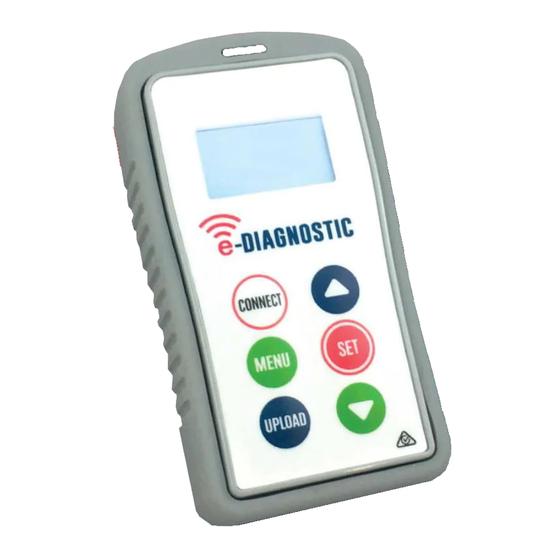
Specifications
High impact PC casing.
Silicone rubber cover.
IP 65 rated.
LCD backlight graphic display.
433.39 MHz bidirectional Transceiver.
Operates from 2 x 1.5V AAA batteries.
Activation and signal strength
1. Press the MENU button and you will see two
selections, Open RX will be highlighted, press SET
to select. You can now monitor the e-Loop
activation.
2. When the trip level is exceeded, the screen will
display the activation and the level that it tripped
at for 2 seconds, to exit this mode just press the
MENU button again.
3. To test for background interference, press the
MENU button, now scroll using the down arrow
until Signal Strength is displayed. Press SET to
select or MENU to exit.
4. Low background noise is indicated as 1 to 2 bars, if
you see more than 2 bars displayed constantly, you
may have an interference problem.
This Signal Strength bar graph will also display the
signal strength from our transmissions of remotes or e-
Loops. Although this will only be a short burst, it can be
quite useful in determining signal strength at the
receiver end.
T: +44 (0) 288 639 0 693
E. sales@aesglobalonline.com
www.aesglobalonline.com
Advertisement
Table of Contents

Summary of Contents for AES e-DIAGNOSTIC
- Page 1 Specifications High impact PC casing. Silicone rubber cover. IP 65 rated. LCD backlight graphic display. 433.39 MHz bidirectional Transceiver. Operates from 2 x 1.5V AAA batteries. Activation and signal strength 1. Press the MENU button and you will see two selections, Open RX will be highlighted, press SET to select.
- Page 2 Connecting to an e-Loop Hold the remote close to the e-Loop and press the CONNECT button. If pairing is successful, Pair Success will display and the red LED will illuminate on the e-Loop. If not successful, the screen will display Timeout. Now press the MENU button.
- Page 3 Altering XYZ axis NOTE: We only recommend altering the XYZ axis for complex sites where you need less activation from a particular direction, such as the exit road being in close proximity to an entry road. In this instance we would reduce the X field direction so that a passing vehicle in next lane will not trigger the e-Loop.
- Page 4 Changing Radar settings NOTE: Only available for EL00C-RAD and EL0IC-RAD versions. Please contact the technical department before altering any radar settings, doing so may cause the e-Loop to be unreliable. 1. After making connection, scroll to Radar Settings and press the SET button.
- Page 5 The sixth option is Radar INT - this is used to adjust the time between radar reads when in presence mode. The default value is 60 seconds and can be adjusted from 15 to 180 seconds. Press SET to alter. Use Up or Down buttons to change and SET to confirm.
Need help?
Do you have a question about the e-DIAGNOSTIC and is the answer not in the manual?
Questions and answers