Advertisement
Quick Links
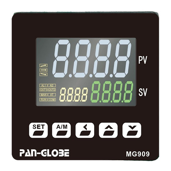
Series BI-MODE output - AR
Digital Controller
Instruction Manual
1.
Attention
1. Attention! Electrical hazard!
Caution
Do not touch the AC power terminal after the controller is electrified to avoid electric shock.
When implementing controller power wiring, make sure the power is off first!
1. Please do not use this product in places full of explosive and combustible gases.
2. Before connecting the power supply, please confirm whether the voltage is within the rated range and
Wanrning
whether the wiring terminals are correct, or the controller may be seriously damaged after the power supply.
3.The maximum torque of the terminals should not exceed 8KG.
4.It is strictly forbidden to decompose, modify or repair the product.
5. Please do not use in the following circumstances:
● where the temperature changes dramatically.
● places where humidity is too high and water is produced .
● a place where the vibration or impact is very strong Where corrosive gases or dust are present.
● splash of water, oil and chemicals.
6.Wiring should be kept away from high-voltage, high-current power lines to avoid interference.
7. Please note that the outer shell of the body is eroded by organic solutions, strong acids, strong alkalis.
2.
Functions and Performance
Power and Voltage
AC85-265V,50/60Hz(DC power is optional)
Power Consumption
6VA Max
Control Mode
PID、PD、PI、P、Fuzzy(OPAD)
Environment temperature
Environment Humidity
Specification
Thermocouple and thermal resistance can be switched at will (no hardware modification required)
Signal Input:
Adopt theslope value to compensate the temperature
Add artificial intelligence
The controller can transmit PV, SV and MV in 6 ways to positive or negative side, and it has
form a double output ratio control system
(5)
The controller has parameter running specifications RUN to choose the Work or Stop.
(6)
Output soft start function
3.
Panel cutout and Dimension
Panel cutout
Size
Model
Display Precision
anti-overshoot coefficient
Thank you for purchasing (A)MG900 series controller.
This manual mainly explains some necessary attention in installation and
wiring .Before operation , please read this manual first to fully understand
the operation of this product.Please take this manual with you for reference
at any time.
±0.2%FS
Input
Universal input(T/C、PT100、Analog signal)
Output
Relay, SSR, 4-20mA
Sampling time
Dimension
a menu of ratio coefficient to
Advertisement

Summary of Contents for Pan-Globe MG900 Series
- Page 1 Series BI-MODE output - AR Thank you for purchasing (A)MG900 series controller. This manual mainly explains some necessary attention in installation and Digital Controller wiring .Before operation , please read this manual first to fully understand the operation of this product.Please take this manual with you for reference at any time.
- Page 2 Operation Instruction Window Name Symbol Name Name Function Function Symbol When lit Rampup light,it indicates that When changing parameter, confirm Loop/confirmation Rampup indicator the program to rampup. parameter When lit Soak light,it indicates that Auto/Manua Switch between automatic and manual control Soak indicator the program to soak Moving set point digit(thousand,hundred,...
- Page 3 Zone internal alarm Deviation lower alarm Absolute value lower alarm Thermo couple breaking Zone external alarm (No alarm at the first time) (No alarm atthe first time) (No alarm at the first time) alarm AL>0 AL>0 HY=0 chart HY=0 chart HY=0 chart HY=0 chart Program segment ending...
- Page 4 Operation Instructions 1. Basic Operation Step1:Measure the types of the input signal Press enter lever2 In the INP option,press Press to choose the input Press to confirm amend ,SV monitor will flash signal(refer to 5.Input Type table) Step2:Alarm mode setting Ad1(Ad2) Press enter lever2 Under Ad1 option,press...
- Page 5 Access Parameter Menu Schematic diagram of each level (how to switch level *Return to level 0(operation setting level if no pressing any key within 30sec Operation set up level for 3sec Press Press Press Press Press Press Press Iutput calibration Program parameter Output calibration Parameter control...
- Page 6 HC:BI-MODE output H:Reverse output Porportional band(%) Alarm 1 mode selection Integral time(second) I set to 0 is the integration close Alarm 1 HYS setting Differential time(second) D set to 0 is the different close Alarm 2 mode selection Cold control Integral time(second) I set to 0 is the integration close Alarm 2 HYS setting...
-
Page 7: Working Mode
Application Example Illustration Example 1,Output gap application Parameter setting: MG900 double output controller support double PID control,PID instruction are: Heating side:proportion bandP1, integral timeI1,differential timeD1,working peridCTY1 Cooling side:proportion bandP2, integral timeI2,differential timeD2,working peridCTY2 working mode Heating side Cooling side working mode Heating side Cooling side working mode... - Page 8 Example 3:Temperature offset Blank area: surface temperature 2.Using the PVOS three point complement function, set(TM=100° (practical application area) TS=-5°),(TM2=150° TS=-6°),(TM3=200° TS=-7°), Black area: T/C measure temperature T/C measure temperature Surface temperature Relation (actual heating area) T/C temperature is 5°higher than the actual T/C temperature is 6°higher than the actual T/C temperature is 7°higher than the actual There is a temperature difference between blank area: surface temperature and T/C...
- Page 9 (AMG)MG900 Series MODUS Communication Protocol 1.Protocol Introduction 1.1 Scope of selection: pan-globe M2000 series communication instrument 1.2 Work realization: data exchange between instrument and host computer (instrument can only be used as slave to receive interrogation and reply) 1.3 Serial transmission mode: RTU 1.4 Transmission interface: RS485...
- Page 10 Alarm1 Status Alarm2 Status Alarm3 Status Program menu address: CX=(X-1)*4+200,X is segment number:C60,X=60,Input Range LSP~USP; TX=(X-1)*4+201,Input Range(0~3600) OUX=(X-1)*4+202,Input Range(0~100) The override of CX is 10,the override of TX ,OUX is 1 INP(INP2)Input reference Table...
Need help?
Do you have a question about the MG900 Series and is the answer not in the manual?
Questions and answers