Table of Contents
Advertisement
Quick Links
Advertisement
Table of Contents

Related Manuals for WABCO SMARTTRAC MM1543


Summary of Contents for WABCO SMARTTRAC MM1543
- Page 1 SMARTTRAC™ HYDRAULIC ANTI-LOCK BRAKING SYSTEMS MAINTENANCE MANUAL MM1543...
-
Page 3: Table Of Contents
Symbols Used in this Document ........................5 How to Obtain Additional Maintenance, Service and Product Information ............6 How to Obtain Parts and Kits ..........................6 WABCO TOOLBOX PLUS™ Software ......................6 WABCO Academy ..............................6 WABCO Online Product Catalog ........................6 Your Direct Contact to ZF CVS ..........................7 Safety Information. - Page 4 Component Replacement............................32 Component Removal and Installation ......................32 Brake Bleeding Procedures ..........................36 Appendix I..................................52 SPN/FMI Codes ...............................52 Appendix II.................................63 Aftermarket Programming ..........................63 Minimum Requirements for Aftermarket Programming ..................63 Aftermarket Programming Procedures ......................64 This publication is not subject to any update service. Information contained in this publication was in effect at the time the publication was approved for printing and is Edition 1 subject to change without notice or liability.
-
Page 5: General Information
Important information, notices and/or tips Reference to information on the Internet Descriptive text – Action step Action step 1 (in ascending order) Action step 2 (in ascending order) Ö Result of an action • Listing Indicating the use of a tool / WABCO tool... -
Page 6: How To Obtain Additional Maintenance, Service And Product Information
Refer to the Society of Automotive Engineers (SAE) website to find all current SAE documents and standards applicable to WABCO products (such as SAE J447 and SAE J908 at www.sae.org). Refer to the National Highway Traffic Safety Administration (NHTSA) website to find all current documents referenced in the manual at www.nhtsa.gov. -
Page 7: Your Direct Contact To Zf Cvs
General Information Your Direct Contact to ZF CVS ZF CV Systems North America LLC 1220 Pacific Drive Auburn Hills, MI 48326 Customer Care Center: (855) 228-3203 www.zf.com/cv wabconacustomercare@zf.com... -
Page 8: Safety Information
Safety Information Safety Information Provisions for a safe work environment Only experienced, trained and qualified automotive technicians may carry out work on the vehicle. „ Read this publication carefully. „ Follow all warnings, notices and instructions to avoid personal injury and property damage. „... -
Page 9: Introduction
This manual provides service and repair procedures for WABCO’s SmartTrac™ hydraulic anti-lock braking system for medium-duty trucks, buses and motor home chassis. Manual Information This manual contains service information for the WABCO SmartTrac™ hydraulic ABS. For earlier versions of WABCO hydraulic ABS, refer to: MM38 C Version HABS „... - Page 10 Introduction 3.3.1 How ABS Works The ABS uses wheel speed sensors to measure wheel speeds. The sensors generate signals that are transmitted to an ECU. If the wheels start to lock, the ECU signals the modulator assembly to regulate the brake pressure of each locking wheel.
- Page 11 HSA grade threshold parameters may be modified in the Transmission ECU. These parameters must be reviewed with the transmission manufacturer prior to making any modifications in order to ensure safe operation. 3.3.8 System Layout A typical WABCO SmartTrac™ hydraulic ABS installation is illustrated below. BRAKE BRAKE MASTER CYLINDER...
-
Page 12: System Components
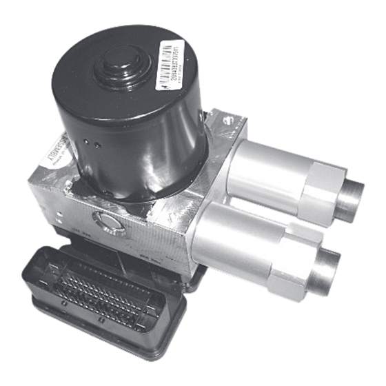
Introduction WABCO requires that the motor axis is positioned at an angle between +0 degrees and +10 degrees with the horizontal plane, with the motor end pointing up and between -20 degrees and +20 degrees of rotation of the motor axis. Contact the OEM or WABCO for additional information regarding the modulator assembly’s orientation. - Page 13 Introduction 3.4.2 Modulator Assembly CAUTION The modulator assembly contains brake fluid. Handle the modulator assembly with appropriate care. Do not expose the modulator assembly to impact loads or excessive vibrations. Do not blow compressed air into the hydraulic ports. Mishandling the modulator assembly may lead to component damage and system failure.
- Page 14 Introduction 3.4.3 Sensors 3.4.3.1 Sensor with Molded Socket Used to measure the speed of a tooth wheel rotating with the vehicle wheel. „ Produces an output voltage proportional to the wheel speed. „ 1004685a 3.4.3.2 Sensor Spring Clip Holds the wheel speed sensor in close proximity to the tooth wheel. „...
- Page 15 Introduction 3.4.3.4 Steering Angle Sensor The steering angle sensor (SAS) is part of the ESC system. The SAS delivers the driver’s steering input „ (steering wheel position) to the ECU using a dedicated ESC system internal datalink. The ECU supplies the sensor with voltage and ground.
- Page 16 Introduction 3.4.3.7 ABS and ATC Warning Lamps Located on the vehicle instrument panel. „ The ABS warning lamp illuminates for 3 seconds while performing a self check when the ignition is „ turned on. It also illuminates when there is a fault. The ATC warning lamp will remain on continuously if ATC is disabled due to a failure.
-
Page 17: Troubleshooting And Testing
4.1.1 General Information There is no regularly scheduled maintenance required for the WABCO SmartTrac™ hydraulic ABS unit. However, ABS does not change current vehicle maintenance requirements. For example, it is important that the vehicle brake fluid level be correctly maintained and regularly changed per the vehicle manufacturer’s... -
Page 18: Wiring Diagrams
Troubleshooting and Testing Wiring Diagrams 4.2.1 System Wiring Information The SmartTrac™ hydraulic ECU connector pin identification is below. Wiring may vary according to the vehicle. Refer to the vehicle specifications in the vehicle manual for specific wiring diagrams. The SmartTrac™ hydraulic ABS wiring diagram appears on the next page. PIN IDENTIFICATION FOR HYDRAULIC ABS WIRE HARNESS CONNECTORS TO THE ECU 2 3 4 5 6 7 8 9 10 11 12 13 14 15 33 34 35 36 37 38 39 40 41 42 43 44 45 46... - Page 19 Troubleshooting and Testing WIRING DIAGRAM SmartTrac™ HYDRAULIC ABS 33 45 46 43 42 36 37 8 14 22 29 18 19 12 13 1 32 47 SENSOR SENSOR SENSOR SENSOR FRONT FRONT REAR REAR RIGHT LEFT RIGHT LEFT (KL_30) BATT (KL_31) GND (KL_15) IGNITION (CAN_1 H) J1939 H...
-
Page 20: System Diagnostics
The TOOLBOX™ Software is available for purchase at https://wabco.snapon.com. Follow the instruction and correctly install the software. Once you have TOOLBOX™ Software installed on your computer, follow the on-screen repair information to make the necessary repairs or replacements. - Page 21 Troubleshooting and Testing The log will display the stored and active faults. Active faults that occur after the screen is displayed will not appear until a screen update is requested. After making the necessary repairs, use the Clear DTCs button to clear the fault. Cycle the ignition and restart the program to check for faults that are still active.
-
Page 22: Testing The System
Troubleshooting and Testing Help SmartTrac™ Maintenance Manual: Opens SmartTrac™ Hydraulic ABS Maintenance Manual. Contact Information: Displays the WABCO contact information. About: Displays the version information about the SmartTrac™ hydraulic software in TOOLBOX™ Software. Testing the System This section of the manual contains information for testing the SmartTrac™ hydraulic unit with TOOLBOX™... -
Page 23: Standard Testing
Tire Size Range For correct hydraulic ABS operation, front and rear tire sizes must be within 8% of each other. Contact the WABCO Customer Care Center at 855-228-3203 if you plan a tire size difference greater than 8%. Calculate the tire size with the following equation: % Difference = ((RPM Steer/RPM Drive) –... -
Page 24: Voltage Check
Verify that the resistance between pin 47 and chassis ground is less than 1 ohm. „ Perform load (impedance) test. Contact the WABCO Customer Care Center at 855-228-3203 for simple ways to perform load tests. „ 4.8.3 Sensor Output Voltage Check Sensor output voltage must be at least 0.2 volt AC at 30 rpm. - Page 25 Troubleshooting and Testing Table A: Sensor Check Pins Sensor 47-Pin Harness Connector Left Front 45 and 46 Right Front 33 and 34 Left Rear 36 and 37 Right Rear 42 and 43 4.8.4 Sensor Resistance The sensor circuit resistance must be between 900 and 2000 ohms. Measure the resistance at the sensor connector, or at the pins on the ECU connector, as follows: Turn the ignition OFF.
-
Page 26: Esc Testing
Troubleshooting and Testing ESC Testing 4.9.1 ESC CAN Network Testing The ECU, SAS and ESC module are all connected on propriety CAN network with internal terminating resistors on each one of these components. A failure to one of the components will cause others to fault out. HECU MODULE 4010628a... - Page 27 4012659a 4.9.1.2 ESC Information Available in WABCO TOOLBOX™ Software 12.7 or Higher ESC Information can be accessed through WABCO TOOLBOX™ Software 12.7 or higher under Components, ESC. To access the ESC Information: If you are using TOOLBOX™ Software version 12.7 or higher, click on the “Components” button. A drop- „...
- Page 28 Troubleshooting and Testing 4015710a 4015711a...
-
Page 29: Steering Angle Sensor (Sas) Testing
4.10 Steering Angle Sensor (SAS) Testing Electrical Checks The following tests are for WABCO SAS Only. Disconnect SAS and check terminating resistance across Pin 1 and Pin 2 of the SAS. „ For the following checks, all the ECU and ESC module connectors must be plugged in as the ECU provides all voltage, ground and CAN communications. - Page 30 Troubleshooting and Testing STEERING ANGLE SENSOR CAN-HIGH 180 OHM CAN-LOW +U-BATT 4010631a STEERING ANGLE SENSOR CONNECTOR 4007216a Circuit CAN-Low Terminating Resistor CAN-High CAN-High Power Ground Do not load test across power and ground at the SAS. BENDIX STEERING ANGLE SENSOR CONNECTOR LOOKING INTO WIRE HARNESS CONNECTOR 4011908a...
-
Page 31: Ecu Circuit Testing
Troubleshooting and Testing Circuit Ground Power CAN-High CAN-Low 4.11 ECU Circuit Testing Electrical Checks Verify vehicle batteries, charging system and fuses are in good working condition. „ Load test battery and ignition circuits to ground at the ECU harness using a 2-4 amp sealed lamp and „... -
Page 32: Component Replacement
-40° to 300°F (-40° to 150°C). WABCO provides sensor lubricant in a packet with each sensor service part. Lubricants approved for use on WABCO sensors and spring clips are as follows. - Page 33 Install the fasteners used to hold the sensor cable in place. Apply a WABCO-recommended lubricant to the sensor spring clip and sensor. Install the sensor spring clip. Verify that the spring clip tabs are on the inboard side of the vehicle.
- Page 34 Press the sensor spring clip into the sensor bracket, located on the rear axle, until it stops. Verify that the tabs are on the inboard side. Apply a WABCO-recommended lubricant to the sensor. Push the sensor completely into the spring clip until it contacts the tooth wheel.
- Page 35 WABCO recommends that the motor axis makes an angle between +0 degrees and +10 degrees with the horizontal plane, with the motor end pointing up and between -20 degrees and +20 degrees of rotation of the motor axis. Contact the OEM or WABCO for additional information regarding modulator assembly orientation.
-
Page 36: Brake Bleeding Procedures
In some cases, for example, if you are replacing only the modulator assembly, it may not be necessary to bleed the master cylinder. If you have any questions, please contact the WABCO Customer Care Center at 855-228-3203. - Page 37 Component Replacement CAUTION Hydraulic brake fluid is a caustic substance. Skin contact with hydraulic brake fluid can cause irritation. Do not let hydraulic brake fluid touch any painted surfaces, as it will remove the paint. Hydraulic brake fluid may also damage certain non-metal surfaces. Do not let brake fluid get on brake pads, rotors, shoes, or drum.
- Page 38 Component Replacement Below are the steps for the pressure fill, bleed process and using the WABCO TOOLBOX™ Software version 12.7 to bleed the hydraulic brake system and SmartTrac™ ABS Module. The WABCO TOOLBOX™ Software version 12.7 and beyond will support the following bleed procedure.
- Page 39 Component Replacement Submerge the loose end of the tubing in a container of clean hydraulic brake fluid. Loosen the bleeder fitting until fluid begins to flow (about 3/4 turn). Allow the hydraulic brake fluid flow out of the fitting until it is free of air bubbles.
- Page 40 Component Replacement 11. After opening the SmartTrac™ screen, select the EOL menu and then select Bleed Procedure. Refer to the “System Diagnostics” section of this manual for additional information. 4013019a The bleed procedures Pump Flush, ESC Switching Sequence FRONT Axle and ESC Switching REAR Axle will actuate the SmartTrac™...
- Page 41 Component Replacement 5.2.4 Manual Bleed Procedure Below are the steps for the manual fill and bleed procedure using the WABCO TOOLBOX™ Software version 12.7 to bleed the hydraulic brake system and SmartTrac™ ABS module. WARNING Do not let the brake fluid in the master cylinder get below the minimum level during the bleeding operation.
- Page 42 Component Replacement Repeat Step 7 for the remaining three wheel ends. Ensure all four wheel end bleed fittings are closed. 1004710a Open the TOOLBOX™ Software using the icon, then open the SmartTrac™ screen by selecting the Tractor icon. 4011996a 4013018a...
- Page 43 Component Replacement 10. After opening the SmartTrac™ screen, select the EOL menu and then select Bleed Procedure. Refer to the “System Diagnostics” section of this manual for additional information. 4013019a The bleed procedures Pump Flush, ESC Switching Sequence FRONT Axle and ESC Switching REAR Axle will actuate the SmartTrac™...
- Page 44 Component Replacement 5.2.5 Steering Angle Sensor (SAS) — WABCO Only Removal WARNING Park the vehicle on a level surface. Block the wheels to prevent the vehicle from moving. Support the vehicle with safety stands. Do not work under a vehicle supported only by jacks. Jacks can slip or fall over.
- Page 45 Component Replacement Install the SAS with the connector facing the same direction as the original. Place the SAS over the steering column shaft and slide it into place with the SAS tab placed in the groove that is machined on the steering column shaft.
- Page 46 Component Replacement ± 5° -5° +2° -2° +2° -2° 4010609a Remove the two mounting capscrews and nuts. Remove the ESC module. ESC modules are installed by the vehicle manufacturer close to the vehicle center of gravity. Depending on the vehicle manufacturer, the ESC module might face towards the front of the vehicle or rear.
- Page 47 To prevent incorrect activations, SAS Calibration and ESC Initialization must be done separately. It is necessary to perform the SAS calibration prior to the ESC initialization. For any questions or assistance, please contact the WABCO Customer Care Center at 855-228-3203 or visit www.zf.com/cv for further details.
- Page 48 Component Replacement 4015712a To access the ESC EOL: From the bar menu at the initial screen, click on the “Components” button. A drop-down menu will „ appear. Select the option “ESC.” 4015713a...
- Page 49 The vehicle needs to be sitting still during SAS calibration. To complete the SAS Calibration, position the steer axle tires straight ahead and click “SAS Calibration”. Upon successful calibration, the status box will display “SAS Calibration message sent successfully”. WABCO TOOLBOX - ESC Menu 4012626a...
- Page 50 Check the message box that appears. The ATC lamp will start blinking to inform driver ECU is in learning mode. WABCO TOOLBOX - ESC Menu 4012627a Carefully follow the instructions that appear in the message box. Once the ESC initialization is started, the messages will automatically change as the requirements are met.
- Page 51 Component Replacement When the ignition is turned back ON, check that no active or stored faults are logged in the ECU and that the ABS and ATC/ESC warning lamps are OFF. To check ESC system status, open the ESC menu and click the “ESC Info” button. 4015716a The ESC Information screen will display the ESC straight driving, Steering Ratio Learning, and ESC End of Line Status as “Complete”.
-
Page 52: Spn/Fmi Codes
Appendix I Appendix I SPN/FMI Codes Refer to the following SPN and FMI codes to diagnose SmartTrac™ hydraulic ABS-related issues. You must contact the WABCO Customer Care Center at 855-228-3203 for all faults and approved repair instructions. Component Fault Description... - Page 53 Appendix I Component Fault Description Repair • Reset the ECU by cycling the ignition or by using the reset option in the TOOLBOX™ Software. ECU/System • If the fault persists, check the ABS ECU powers and ECU internal failure component grounds.
- Page 54 Appendix I Component Fault Description Repair • Reset the ECU by cycling the ignition or by using the reset option in the TOOLBOX™ Software. Pressure sensor Internal sensor • If the fault persists, check the ABS ECU powers and 1043 reference failure grounds.
- Page 55 Appendix I Component Fault Description Repair • Check for the correct sensor setting (air gap 0.2 to 1.7 mm). Air gap too large • Check the bearing clearance and tone ring run out. Tone ring damaged Eliminate the cause of the increased air gap and correct the or corroded sensor setting.
- Page 56 Appendix I Component Fault Description Repair • Check for the correct sensor setting (air gap 0.2 to 1.7 mm). • Check the bearing clearance and tone ring run out. Eliminate the cause of the increased air gap and correct the sensor setting.
- Page 57 Appendix I Component Fault Description Repair • Check for the correct sensor setting (air gap 0.2 to 1.7 mm). • Check the bearing clearance and tone ring run out. Air gap too large Eliminate the cause of the increased air gap and correct the Tone ring damaged sensor setting.
- Page 58 Appendix I Component Fault Description Repair Sensor defective • Check the sensor wiring harness and connection for Open connection damage/interruptions. Sensor impedance out of normal • Replace sensor if necessary. operating range • Check for damaged or missing teeth on tone ring. Tone ring damaged or corroded •...
- Page 59 Appendix I Component Fault Description Repair • Check for the correct sensor setting (air gap 0.2 to 1.7 mm) • Check the bearing clearance and tone ring run out. Eliminate the cause of the increased air gap and correct the Wheel speed sensor setting.
- Page 60 Appendix I Component Fault Description Repair • Check for the correct sensor setting (air gap 0.2 to 1.7 mm). • Check the bearing clearance and tone ring run out. Eliminate the cause of the increased air gap and correct sensor setting. Noise on sensor output signal •...
- Page 61 • Check for corroded or damaged wiring between SAS and angle signal is ESC module. not available after • Contact the WABCO Customer Care Center at ignition on. 855-228-3203 to check the parameter setting of the ECU and SAS compatibility.
- Page 62 520210 ESC Module • Verify the SAS and ESC module are correctly mounted, ESC system detects leveled and in the correct location. Contact the WABCO a plausibility issue Customer Care Center at 855-228-3203 to ensure the while driving ESC module and SAS is in accordance with ABS ECU parameters.
-
Page 63: Aftermarket Programming
TOOLBOX™ 12.7 Software. The version of TOOLBOX™ Software being used can be found at the top of the TOOLBOX™ Software window. If you do not have the latest TOOLBOX™ Software, you can purchase it at http://wabco.snapon.com. Aftermarket programming requires configuration files which can be downloaded without charge at: https://wabco.snapon.com. -
Page 64: Aftermarket Programming Procedures
The ABS lamp will remain on until the vehicle has been driven above 4 mph (6 km/h). Step 3: Acquire the required configuration file from https://wabco.snapon.com. Begin by either creating an account or logging into an account created during a previous purchase from the... - Page 65 Appendix II If you purchased TOOLBOX™ Software, then you already have an account and that account information should be used to log in. 4013302a Click the Aftermarket Programming Configuration Files button at the top of the screen. If TOOLBOX™ Software is not available at the point of service, it can be purchased by clicking the TOOLBOX™...
- Page 66 Appendix II 4015716a The next screen will show the configuration file details linked to the part number and VIN combination entered. Verify the VIN, part number and SmartTrac™ hydraulic ABS module functionality matches the SmartTrac™ hydraulic ABS module being replaced. If this information is correct, click the Add to shopping cart button.
- Page 67 Appendix II Clicking on “Go To Shopping Cart” or “Check Out” symbol will take you to the contact details page that need to be filled out to process the order. 4013308a The first step in the checkout process is to verify contact information. The information will automatically populate based on login information;...
- Page 68 Appendix II The order will be processed and a link to download the configuration file will be displayed. Click the hyperlink to download the configuration file. 4013311a The file extension “.HY” is specifically for the SmartTrac™ hydraulic ABS module only. Ensure the file has this.
- Page 69 Begin by verifying you have the latest version TOOLBOX™ Software. First locate the software version on the WABCO label on the SmartTrac™ hydraulic ABS module. An example of the cab ECU label is shown, and the ECU software version is circled.
- Page 70 Appendix II A message will be displayed indicating that the SmartTrac™ hydraulic ABS module will be changed as a result of programming. Click “Yes” to continue with programming the SmartTrac™ hydraulic ABS module. Aftermarket Programming will change the SmartTrac™ hydraulic ABS module parameters. 4013316a The Aftermarket Programming application will then locate the configuration file.
- Page 71 Information obtained in this manual was in effect at the time the publication was approved for printing and is subject to change without notice or liability. WABCO reserves the right to revise the information presented or to discontinue the production of parts described at any time.
- Page 72 CVS unites ZF’s former Commercial Vehicle Technology and Commercial Vehicle Control Systems divisions, the latter being formed following ZF’s acquisition of WABCO in Spring 2020. For more information, visit: www.zf.com/cv...
Need help?
Do you have a question about the SMARTTRAC MM1543 and is the answer not in the manual?
Questions and answers