Table of Contents

Related Manuals for Neilsen CT2205


Summary of Contents for Neilsen CT2205
- Page 1 80LB WALK BEHIND SPREADER CT2205 INSTRUCTION MANUAL SAVE THESE INSTRUCTIONS AND PRECAUTIONS. READ ALL PRECAUTONS AND INSTRUCTIONS BEFORE USE. Cannon Tools Limited Address: 20 Station Road, Rowley Regis, West Midlands, B65 0JU.U.K.
-
Page 2: Ec Declaration Of Conformity
In case of alteration of the machine, not agreed upon by us, this declaration will lose its validity. Product description: WALK-BEHIND SPREADER Model: CT2205 Applicable EC Directives: EC Machinery Directive 2006/42/EC Harmonized standards EN ISO 12100:2010, EN ISO 13854:2019, EN ISO 14120:2015, EN ISO 13857:2019 20 Station Road, Rowley Regis, West Midlands, B65 0JU.U.K. -
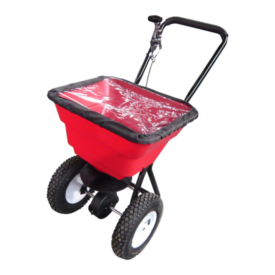
Page 3: Specifications
1. SPECIFICATIONS Capacity: 80LB Spread Width: 10'-12'/3048mm-3658mm Pneumatic Tire: 12" Heavy duty Nylon gear Rate setting control on handle for precise adjustments Accessories: screen & rain cover 2. GENERAL SAFETY INSTRUCTIONS Warning: When using tool, basic safety precautions should always be followed to reduce the risk of personal injury and damage to equipment. - Page 4 CONDITIONS. We recommend the machine is not used during winds. This may affect the spreading pattern. DRESS PROPERLY. Do not wear loose clothing, gloves, scarfs, neckties or jewellery (rings, wrist watches), which can be caught in moving parts. DO NOT OVERREACH. Keep proper footing and balance at all times when using the machine.
-
Page 5: Controls And Features Identification
3. CONTROLS AND FEATURES IDENTIFICATION Read this owner’s manual before operating the equipment. Familiarize yourself with the location and function of the controls and features. Save this manual for future reference. 1) Flow Control – Controls the flow of material being spread. 2) Handle –... - Page 6 4. ASSEMBLY AND OPERATING INSTRUCTIONS 1. HELPFUL HINTS: READ THE INSTRUCTIONS BEFORE ASSEMBLY If your spreader does not spread evenly, be sure the FRONT on the gear box points to the front of the spreader. The impeller must turn clockwise. Reversing the gear box will cause the impeller to turn counter clockwise.
- Page 7 STEP 1: Install impeller onto the Gear Box & Axle Assembly. Insert Screw M4x20 through impeller then through Gear Box Axle.
- Page 8 STEP 2: Attach the Wheel Assembly Frame on each side of the Gear Box Axle and Fixing Connecting Rod, insert two bolts M6x35 into the Fixing Connecting Rod through Wheel Assembly Frame. Make sure the hole on Axle of Gear Box is on the right side when assembly as shown.
- Page 9 STEP 3: Insert Inner Axle Bushing into Outer Axle Bushing and make sure they are tight neatly. Install right Wheel Assembly to right Axle using bolt M5x45 and lock nut M5, and then install the Cap onto right Axle using a wooden or rubber hammer.
- Page 10 STEP 4: Insert Upper Handle into the Support Leg and tighten using bolts M6x40 and Lock Nuts M6. NOW GO BACK AND TIGHTEN ALL NUTS AND BOLTS STARTING WITH FIRST STEP. DO NOT OVER TIGHTEN.
- Page 11 STEP 5: (1) Insert the Steel Wire head of control cable into the small hole on Gauge and Lever Assembly. (2)Release two bolts M5x10 and lock nuts on Press Plate. (3) Put the Plastic Tube into the slot of Press Plate. (4) Tighten two bolts M5x10 and lock nuts again.
- Page 12 STEP 6: ADJUSTMENTS. When you have finished all above steps, and if you find the holes at the bottom of hopper can close and open completely by using the handle . You don't need to do the following steps. If it do not close and open completely, you may need to do the following steps.
-
Page 13: Maintenance And Storage
5. MAINTENANCE AND STORAGE MAINTENANCE ● Rinse/dry inside and outside of the aerator spreader after each use. ● Regularly grease axle and wheel bearing area or when needed. ● Periodically check all fasteners for tightness. ● Annually clean and lightly lubricate spike assembly and shaft or when needed. ●... -
Page 14: Parts Drawing
6. PARTS DRAWING... -
Page 15: Parts List
PARTS LIST Ref# Description Ref# Description Carriage Bolt M6x25 Support Leg External-tooth Washer Ø8 Wheel Assembly Frame(Right) Gauge and Lever Assembly Thin Washer Adjust Handle Pole Pneumatic Wheel Adjust Handle A Flat Washer Ø16 Adjust Handle B Axle End Cover Screw M4x18 Inner Axle Bushing Handle Grip... - Page 16 CANNON TOOLS LTD Add: 20 station road, Rowley Regis, west midlands,B65 0JU.U.K. Made in China...