Table of Contents
Advertisement
Advertisement
Table of Contents
Troubleshooting

Summary of Contents for MSI BEAHM 160-A
-
Page 2: Table Of Contents
Table Of Contents List of Figures ..............................3 List of Tables ..............................3 Purpose ................................. 4 Overview ............................... 4 Contents ................................ 4 Installation ..............................4 Safety ................................5 User Alerts ..............................5 Set Up and Configuration ..........................6 System Controls and Features ........................6 Parameter Settings ............................ -
Page 3: List Of Figures
Tuning Temperature Controllers (Eurotherm Model 3216e) ..............12 Critical Spare Parts (Contact Beahm Designs for pricing) ..............12 Diagnostics (Troubleshooting) ....................... 12 System Schematics ..........................14 Servicing ..............................19 Heating Element ............................. 19 Temperature Controller ......................... 20 Power Controller ............................ 20 Warranty .............................. -
Page 4: Purpose
Purpose The purpose of this document (Original Instructions) is to describe the electrical and software design of the control system for the Hot Air Stations; Models 160-A, 185-A, and 210-A. This document also includes operator instructions. Overview Beahm Designs Hot Air Stations are compact, bench‐top systems designed to deliver precisely controlled heated air through a variety of multi‐port nozzles. -
Page 5: Safety
Safety • Use of eye protection when working with compressed gases and heated materials is advised. • The maximum observed Sound Pressure Level is below 70 dB(A). Caution: high voltage. Remove power and use safety precautions when servicing. Caution: hot surface. Contact may cause burn. Allow to cool before servicing. Caution: pinch point. -
Page 6: Set Up And Configuration
Note: This equipment is not for use in an ATEX environment. Set Up and Configuration Proper sizing of the thermal nozzle is crucial to the optimizing process and repeatability. The following guidelines are recommended methods; however, all applications vary, and several iterations of tooling process development may be required and may not follow all of the recommended guidelines. -
Page 7: Figure 2. Standard Hot Air System (Model 185-A)
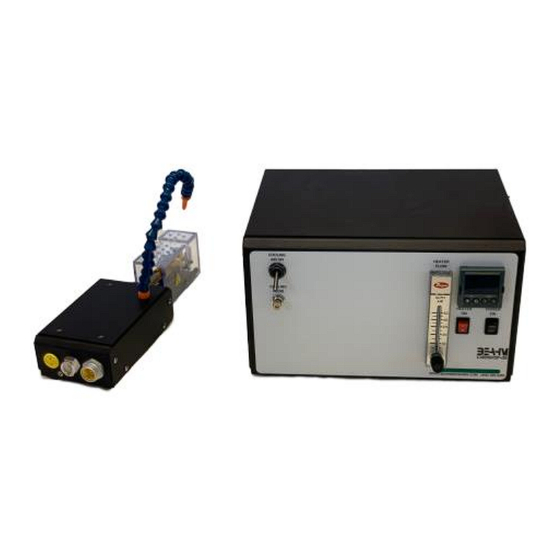
Main power switch Toggles system power and air on and off. Heater Power Switch Toggles heater power on and off. Cooling Air Flow Adjust Controls cooling air flow rate. Cooling Air Toggle Switch Toggles cooling air on/off Heater Air Flow Meter Controls heater air flow rate. -
Page 8: Figure 3. Balloon Development System (Model 210-A)
Figure 3. Balloon Development System (Model 210-A) 210‐A only Description Function Pressure regulator Regulates the pressure at the PRESS/VAC. Port. Pressure gauge Displays the pressure at the PRESS./VAC. Port. Vacuum Gauge Display vacuum at the PRESS./VAC. Port. Rotary Switch Selects pressure or vacuum at PRESS./VAC. port PRESS./VAC. -
Page 9: Parameter Settings
Figure 4: Thermal Nozzles Parameter Settings Temperature Depress and hold the up or down arrow key of the temperature controller to scroll to the desired temperature. After 2 seconds the new value will be accepted and the temperature will ramp to the new set point. Heater Air Flow Rotate the flow meter knob clockwise or counterclockwise until the meter displays the desired value. -
Page 10: System Operation
System Operation Power On 1. Switch MAIN POWER on. 2. Set heater air flow to 20-40 SCFH. 3. Switch HEATER POWER on. a. When the temperature is not within +/- 3 degrees of the set point the error message “TEMPERATURE ERROR” will be displayed. 4. -
Page 11: Maintenance
Maintenance Caution: pinch point/crush hazard. Keep fingers, hands, and clothing clear of moving parts. 1. Use 99% isopropyl alcohol to wipe down the outside of the machine. Do not attempt to clean the inside of the machine. Machine should not be washed down. 2. -
Page 12: Calibration (See Notes Below)
Calibration (See Notes Below) 1. It is recommended that calibration be performed by a certified service, preferably with the system i n the location of use. Calibration procedures are the domain of these service providers. 2. Calibration refers to the process of verifying that each of the systems’ instruments that control a process parameter is within manufacturers’... -
Page 13: Table 6. Diagnostics And Troubleshooting
S.br Break in thermocouple wire Verify all connections from Thermocouple failure controller to remote TC jack Replace thermocouple No heat at nozzle Heater air flow too low Increase air flow Defective heating element Replace heating element. Defective power control Contact Beahm Designs .Err code in display Temperature controller Replace temperature... -
Page 14: System Schematics
System Schematics 14 | P a g e Machine Solutions Inc. 2951 W. Shamrell Blvd. Flagstaff, Arizona 86005 USA Tel: 928.556.3109 Fax: 928.556.3084 • info@machinesolutions.com www.machinesolutions.com •... -
Page 15: Figure 6: System Electrical Schematic 160-A
Figure 6: System Electrical Schematic 160-A 15 | P a g e Machine Solutions Inc. 2951 W. Shamrell Blvd. Flagstaff, Arizona 86005 USA Tel: 928.556.3109 Fax: 928.556.3084 • info@machinesolutions.com www.machinesolutions.com •... - Page 16 16 | P a g e Machine Solutions Inc. 2951 W. Shamrell Blvd. Flagstaff, Arizona 86005 USA Tel: 928.556.3109 Fax: 928.556.3084 • info@machinesolutions.com www.machinesolutions.com •...
-
Page 17: Figure 7: System Electrical Schematic 185-A And 210-A
Figure 7: System Electrical Schematic 185-A and 210-A 17 | P a g e Machine Solutions Inc. 2951 W. Shamrell Blvd. Flagstaff, Arizona 86005 USA Tel: 928.556.3109 Fax: 928.556.3084 • info@machinesolutions.com www.machinesolutions.com •... -
Page 18: Figure 8: System Pneumatic Schematic 160-A
Figure 8: System Pneumatic Schematic 160-A 18 | P a g e Machine Solutions Inc. 2951 W. Shamrell Blvd. Flagstaff, Arizona 86005 USA Tel: 928.556.3109 Fax: 928.556.3084 • info@machinesolutions.com www.machinesolutions.com •... -
Page 19: Servicing
Figure 9: System Pneumatic Schematic 185-A and 210-A Servicing Note: Disconnect system main power and air before servicing any part of the product. Heating Element 1. Remove the top cover of the remote heater enclosure. 2. Disconnect the two electrical quick-disconnects. 3. -
Page 20: Temperature Controller
Temperature Controller Contact Beahm Designs for further diagnostics and instructions. Power Controller Contact Beahm Designs for further diagnostics and instructions. Warranty Beahm Designs Inc. (BDI) products are backed by a 1 year warranty on parts and labor. Warranty is void for any product returned if BDI determines that: a.
Need help?
Do you have a question about the BEAHM 160-A and is the answer not in the manual?
Questions and answers