
Related Manuals for LucidControl DI4DO4

Summary of Contents for LucidControl DI4DO4
- Page 1 LucidControl DI4DO4, User Manual (1.0) 2022/02/03 User Manual LucidControl DI4DO4 USB Module with 4 Digital Input and 4 Digital Output Channels Page 1 of 47...
-
Page 2: Table Of Contents
LucidControl DI4DO4, User Manual (1.0) 2022/02/03 Table of Content Introduction ..............................4 Setup and Installation ..........................4 Safety Information ..........................5 Configurations ............................ 6 Interface and Connection ....................... 7 2.3.1 USB Connection ......................... 7 2.3.2 IO Connection ..........................7 2.3.2.1 Digital Input Channels ..................... - Page 3 LucidControl DI4DO4, User Manual (1.0) 2022/02/03 3.4.1.3.1 inDi0Inverted ....................... 34 3.4.1.3.2 inDi0AddCounter ....................... 34 3.4.1.3.3 inDi0ResetCounterOnRead ..................35 3.4.1.4 inDi0ScanTime ........................35 3.4.1.5 inDi0CountTime ....................... 36 3.4.2 Digital Output Channels ......................37 3.4.2.1 outDi1Value ........................37 3.4.2.2 outDi1Mode ........................38 3.4.2.3...
-
Page 4: Introduction
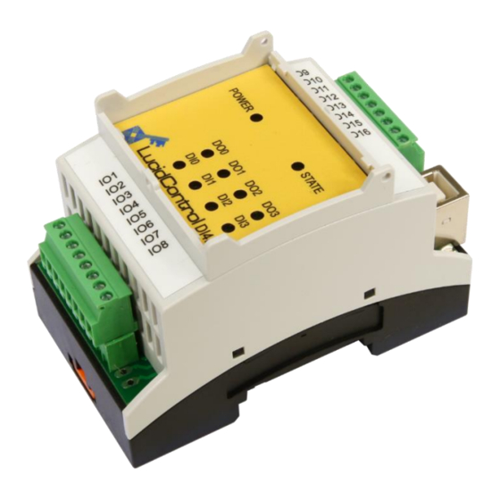
A basic description of the LucidControl product family can be found in the general LucidControl User Manual. This document focuses on functions which are specific for the DI4DO4 USB IO module. 2 Setup and Installation Fig. 1 shows the sketch of the Digital DI4DO4 module with 4 digital input (DI0 to DI3) and 4 digital output (DO0 to DO3) channels. -
Page 5: Safety Information
LucidControl DI4DO4, User Manual (1.0) 2022/02/03 2.1 Safety Information LucidControl complies with regulations and industrial standards active in the EU. To keep the device functional, the following safety and maintenance information must be adhered. The device must only be used for the intended purpose. -
Page 6: Configurations
LucidControl DI4DO4, User Manual (1.0) 2022/02/03 2.2 Configurations The digital output channels of the DI4DO4 are consist of solid-state relays. The digital input channels are available for different threshold levels: Threshold Level LowMax HighMin HighMax 2.5 V 3.5 V 7.5V 10 V 6.0 V... -
Page 7: Interface And Connection
2.3 Interface and Connection 2.3.1 USB Connection LucidControl USB modules are connected to the computer by using a USB 2.0 cable which must not extend a length of 5 m. They are bus powered what means that the host computer supplies the module with power. -
Page 8: Digital Output Channels
LucidControl DI4DO4, User Manual (1.0) 2022/02/03 2.3.2.2 Digital Output Channels Fig. 3 shows the connection of the first digital output channel. When the output is activated, the SSR connects terminal 9 with terminal 10, closing the circuit and switching on the lamp in the shown application. -
Page 9: Setup Of Hard- And Software
The LucidIoCtrl command line tool can be downloaded from our website: www.lucid-control.com/downloads This page provides the command line tool LucidIoCtrl for different architectures. Please see the section 3 of the general LucidControl User Manual for more information about LucidIoCtrl. 2.4.4 First Steps After the module was successfully installed, the green Power LED is switched on signaling that the module is ready for use. - Page 10 LucidControl DI4DO4, User Manual (1.0) 2022/02/03 Windows Examples Setting output channel number 4 to “1”. The module is connected to COM1 LucidIoCtrl -dCOM1 -tL -c4 -w1 [ENTER] Windows requires a different argument for comport numbers >= 10. LucidIoCtrl –d\\.\COM10 –tL –c4 –w1 [ENTER] Reading the states of all digital inputs and outputs LucidIoCtrl –dCOM1 –tL -c0,1,2,3,4,5,6,7 –r [ENTER]...
-
Page 11: Module Operation
LucidControl DI4DO4, User Manual (1.0) 2022/02/03 3 Module Operation 3.1 Digital Input Channel Processing 3.1.1 Real-time Considerations Operating systems for personal computers are not made for deterministic real-time operation. Because of multitasking it cannot be ensured that a task will continue to run within a specified interval. -
Page 12: Reflect Mode
LucidControl DI4DO4, User Manual (1.0) 2022/02/03 In all modes the input values are captured and evaluated after a stable signal has been detected. 3.1.3.1 Reflect Mode The reflect mode acquires the logical input value. Fig. 4 illustrates the processing of the digital input channels in reflect mode. -
Page 13: Edge Detection
LucidControl DI4DO4, User Manual (1.0) 2022/02/03 LucidIoCtrl Command Line Tool Example Set digital input channel 0 to Reflect Mode LucidIoCtrl –dCOM4 –c0 –sinDi0Mode=reflect [ENTER] 3.1.3.2 Edge Detection Digital input channels can operate in edge detection modes. In rising edge mode, the channel is sensitive for low-to-high transitions, in falling edge mode it recognizes high-to- low transitions. -
Page 14: Rising Edge Detection Mode
LucidControl DI4DO4, User Manual (1.0) 2022/02/03 3.1.3.2.1 Rising Edge Detection Mode Fig. 7 shows a digital input signal and the corresponding input value in rising edge detection mode. After the HIGH input signal was detected as being valid, the input value remains pending until it was read by the host computer. - Page 15 LucidControl DI4DO4, User Manual (1.0) 2022/02/03 Fig. 9 illustrates a typical periodical input signal. In count mode all valid pulses are accumulated until the counting interval finishes. Count Fig. 9 Count Mode Fig. 10 shows the same input signal, but with a shorter count interval.
-
Page 16: Count Mode Options
LucidControl DI4DO4, User Manual (1.0) 2022/02/03 Since the input value is updated after count interval has passed it takes 1 second to update the value. Decreasing the count interval results in a faster update of the input value. In Count Mode the value type N is supported. The count value is returned in hexadecimal and decimal format. - Page 17 LucidControl DI4DO4, User Manual (1.0) 2022/02/03 Fig. 11 shows a non-periodic input signal with 10 pulses in total. The counter value is read at 3 times. In the following it is explained how the options affect the count value. Fig. 11 Count Value Add Mode The value "Count"...
-
Page 18: Digital Output Channel Processing
LucidControl DI4DO4, User Manual (1.0) 2022/02/03 3.2 Digital Output Channel Processing 3.2.1 Output Signal Value Inversion Digital output channels have an output signal value and a logical output value. The logical output value is the current state of the output which can be “0” (cleared) or “1” (set). The output signal value is calculated by the output handling. -
Page 19: Operation Modes
LucidControl DI4DO4, User Manual (1.0) 2022/02/03 3.2.3 Operation Modes This section describes the operation of the different output modes and gives examples how the outputs can be controlled. Each of the outputs of the module can work in one of the following modes: •... - Page 20 LucidControl DI4DO4, User Manual (1.0) 2022/02/03 By switching an output periodically on and off it is e.g., possible to control the power consumed by a device and can be used for controlling the power of a pump or a heating element.
-
Page 21: On-Off Mode
LucidControl DI4DO4, User Manual (1.0) 2022/02/03 Cancelation of On-Phase If output processing is stopped while the output is in on- phase (T ), IO Configuration Parameter outDi1CanCancel specifies the behavior of stopping If outDi1CanCancel is set to "off" the sequence completes as shown in Fig. - Page 22 LucidControl DI4DO4, User Manual (1.0) 2022/02/03 Setting the output value to “1” starts processing of the output handling by starting the interval (off-phase). After T has passed the output changes to on-phase and OnDelay OnDelay interval starts. After T time has passed output changes back to off-phase and...
- Page 23 LucidControl DI4DO4, User Manual (1.0) 2022/02/03 restarts the T interval. OnHold LucidIoCtrl Command Line Tool Example Configure output channel 4 for On-Off mode LucidIoCtrl –dCOM4 –c4 –soutDi1Mode=onOff [ENTER] By default, T and T are set to 1s. OnDelay OnHold After writing a “1” to the output value of channel 0 the output will be set after 1s to “1”...
-
Page 24: Commands
LucidControl DI4DO4, User Manual (1.0) 2022/02/03 3.3 Commands LucidControl IO Modules can be accessed by a protocol which is fully documented in the general LucidControl manual. This section describes in detail the commands, which are supported by the DI4DO4 module. -
Page 25: Setiogroup
Status Length Status Returns Execution Status Code documented in the general LucidControl User Manual. 3.3.2 SetIoGroup This command sets the output values of a group of outputs. Tab. 6 lists the digital output channel modes and how the IO value is interpreted. - Page 26 LucidControl DI4DO4, User Manual (1.0) 2022/02/03 Command SetIoGroup Access Write Opcode 0x42 LucidIoCtrl Command Line Tool Call (-tL) LucidIoCtrl –d[COMx] –c[Channels] –tL –w[Values] Channels Comma separated list of channels e.g. –c4,5,6 Values Comma separated list of values to set e.g. -w1,1,0 LucidIoCtrl Command Line Tool Example Set output channel 4 to “1”, output channel 5 to “1”...
- Page 27 Response Frame Status Length Status Returns Execution Status Code documented in the general LucidControl User Manual. Example of SetIoGroup The following request frame sets: • outputs 4 to “1”; output 5 to “1” and output 6 to “0” Request Frame...
-
Page 28: Getio
LucidControl DI4DO4, User Manual (1.0) 2022/02/03 Response Frame Status Length 0x00 0x00 In case of an error, the command returns the Execution Status Code documented in the general LucidControl User Manual. 3.3.3 GetIo This command reads the value or state of an input or output channel. - Page 29 LucidControl DI4DO4, User Manual (1.0) 2022/02/03 Value Description Channel Number of input or output channel (Range: 0 to 3) Value Type Supported Value Types Value Type Value Range Response Len Digital Logic Value 0 / 1 1 Byte (0x00) Digital Counter Value...
-
Page 30: Getiogroup
LucidControl DI4DO4, User Manual (1.0) 2022/02/03 3.3.4 GetIoGroup This command reads the input or output values of a group of IO of the same Value Type. Tab. 6 lists the digital output channel modes and how the IO value is interpreted. - Page 31 LucidControl DI4DO4, User Manual (1.0) 2022/02/03 Value Description Channel Mask Specifies the IO channels to access Channel Bit Position Value 0x01 0x02 0x04 0x08 0x10 0x20 0x40 Channel P1A 0 P1=0x80 Mask P1A = 0x01 Values are bitwise or combined Size of P1 is 1 or 2 bytes.
-
Page 32: Parameters
The parameters are accessible by the SetParam and GetParam command which are described in the general LucidControl User Manual. The DI4DO4 modules mixes input and output channels what made it necessary to rename parameter names and change parameter addresses. 3.4.1 Digital Input Channels 3.4.1.1 inDi0Value... -
Page 33: Indi0Mode
LucidControl DI4DO4, User Manual (1.0) 2022/02/03 LucidIoCtrl –dCOM4 –c0 –ginDi0Value [ENTER] inDi0Value=0 3.4.1.2 inDi0Mode This IO Configuration parameter configures the operation mode of the input. Parameter inDi0Mode Access Read / Write Address 0x1500 Values Input Mode Byte Mode 0x00 inactive... -
Page 34: Indi0Inverted
LucidControl DI4DO4, User Manual (1.0) 2022/02/03 If inDi0Flags is changed by the SetParam command this must be done in a read-modify- write sequence in order to prevent overwriting other bit parameters. 3.4.1.3.1 inDi0Inverted This Bit Parameter configures the input signal value inversion. -
Page 35: Indi0Resetcounteronread
LucidControl DI4DO4, User Manual (1.0) 2022/02/03 Read counter add setting of input channel 0 LucidIoCtrl –dCOM4 –c0 –ginDi0AddCounter [ENTER] inDi0AddCounter=on 3.4.1.3.3 inDi0ResetCounterOnRead This Bit Parameter controls how to update the counter value after it was read. It is relevant in Count Mode only. -
Page 36: Indi0Counttime
LucidControl DI4DO4, User Manual (1.0) 2022/02/03 Parameter inDi0ScanTime Access Read / Write Address 0x1511 Values in µs (micro seconds) Scan 80 µs ≤ T ≤ 1 s Scan Default Value 50,000 (50 ms) Parameter Type 4 Bytes unsigned LucidIoCtrl Command Line Tool... -
Page 37: Digital Output Channels
LucidControl DI4DO4, User Manual (1.0) 2022/02/03 3.4.2 Digital Output Channels 3.4.2.1 outDi1Value This IO Configuration Parameter reflects the value or the state of the output (see Tab. 6). In the case the output is in Reflect mode the outDi1Value contains the logic value of the output. -
Page 38: Outdi1Mode
LucidControl DI4DO4, User Manual (1.0) 2022/02/03 3.4.2.2 outDi1Mode This IO Configuration parameter configures the operation mode of the output. Parameter outDi1Mode Access Read / Write Address 0x1900 Values Output Mode Byte Mode 0x00 Inactive 0x01 Reflect 0x08 On-Off 0x0A Duty-Cycle... -
Page 39: Bit Parameter Outdi1Flags
LucidControl DI4DO4, User Manual (1.0) 2022/02/03 3.4.2.3 Bit Parameter outDi1Flags This IO Configuration Parameter groups configuration settings which are represented by one bit. Parameter outDi1Flags Access Read / Write Address 0x1901 The “bit container” consists of the following parameters. Bit Parameter... -
Page 40: Outdi1Canretrigger
LucidControl DI4DO4, User Manual (1.0) 2022/02/03 This Bit Parameter configures the output on-phase cancelation. Parameter outDi1Flags Access Read / Write Address 0x1901 Bit Parameter outDi1Flags Bit Parameter Bit Postion Values outDi1CanCancel Bit 1 Default Value Parameter Type 1 Bit LucidIoCtrl Command Line Tool... -
Page 41: Outdi1Cycletime
LucidControl DI4DO4, User Manual (1.0) 2022/02/03 3.4.2.4 outDi1CycleTime This IO Configuration Parameter specifies the cycle time T of an output in Duty-Cycle Cycle Mode. Parameter outDi1CycleTime Access Read / Write Address 0x1910 Values in µs (micro seconds) Cycle ≤ T ≤... -
Page 42: Outdi1Ondelay
LucidControl DI4DO4, User Manual (1.0) 2022/02/03 3.4.2.6 outDi1OnDelay This IO Configuration Parameter specifies the on-delay time T of an output in On-Off OnDelay Mode. Parameter outDi1OnDelay Access Read / Write Address 0x1912 Values in µs (micro seconds) OnDelay ≤ T ≤... - Page 43 LucidControl DI4DO4, User Manual (1.0) 2022/02/03 Note Timing limits (see 3.2.2) have to be considered. Page 43 of 47...
-
Page 44: Specification
LucidControl DI4DO4, User Manual (1.0) 2022/02/03 4 Specification Parameter Condition Value Inputs No of Input Channels Inputs - Electrical Characteristics 2.5 V 05MaxLow Input Signal Maximum Low 6.0 V 10MaxLow Level 16.0 V 24MaxLow 3.5 V 05MinHigh Input Signal Minimum High 8.5 V... - Page 45 LucidControl DI4DO4, User Manual (1.0) 2022/02/03 Temperature Storage -20 °C … +70 °C Operation 0 °C … +55 °C Humidity < 85 % RH, non-condensing Module – Housing Dimensions L x W x H 90 x 54 x 62 mm...
-
Page 46: Order Information
2022/02/03 5 Order Information Format of order code: LCTR-DI4-voltage-DO4-I Order Code Product LucidControl USB IO Module with 4 insulated 5V LCTR-DI4-5-DO4-I Input Channels and 4 Solid State Relay (SSR) Output Channels LucidControl USB IO Module with 4 insulated 10V LCTR-DI4-10-DO4-I... -
Page 47: Document Revision
LucidControl DI4DO4, User Manual (1.0) 2022/02/03 6 Document Revision Date Rev. 2022/02/03 Initial documentation deciphe it GmbH Schäferstr. 5 87600 Kaufbeuren / Germany www.lucid-control.com Page 47 of 47...
Need help?
Do you have a question about the DI4DO4 and is the answer not in the manual?
Questions and answers