Table of Contents
Advertisement
Quick Links
◆ Features
Built-in broadband high-stability transmitter for easy measurement of resonant frequency,
l
SWR, and impedance.
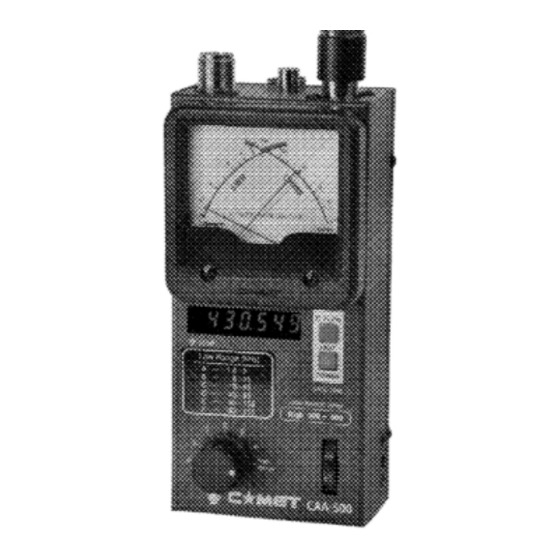
l Cross-needle meter display provides SWR and Impedance information simultaneously.
l 12 hours of continuous use with AA alkaline batteries.
l Hand strap attachment for safety.
Precautions for operation
The CAA-500 has its Impedance Bridge just inside the Output Connector. Never apply power from an
l
external transmitter to the CAA-500. Failure to follow this could cause damage to this product.
The external DC supply voltage must be between 8 to 16 Volts, and the current supplied must be at
l
least 250mA. Never apply DC voltages greater than 16 Volts, nor AC voltage of any kind. Our warranty
does not cover damage caused by the use of an improper power source.
When using AA batteries, the decimal point on the Frequency Counter will blink when the weak
l
batteries are weak. Change batteries as soon as it starts blinking, and change all batteries to improve
the battery shelf life.
Remove the batteries when not in use for extended periods of time
(*some rechargeable batteries, which have 1.2V rated voltage, are not appropriate for long-time continuous
operation).
Thank you for your purchasing our product. This product is made under the
most stringent quality controls. Should there be any breakage in transit,
please do not hesitate to contact the shop from which you purchased this
product for instructions on resolution of the problem.
For your safety, please read this manual carefully for instructions on proper
handling and operation before using.
Instruction Manua l
Advertisement
Table of Contents

Summary of Contents for CAMET CAA-500
- Page 1 Hand strap attachment for safety. Precautions for operation The CAA-500 has its Impedance Bridge just inside the Output Connector. Never apply power from an external transmitter to the CAA-500. Failure to follow this could cause damage to this product.
- Page 2 The cross meter display indicates SWR and impedance simultaneously. ② Frequency Counter This 6-digit LED display indicates the frequency to which the CAA-500 is currently set. ③ Freq Range Selector 6 frequency ranges are provided, yielding coverage of 1.8-500 MHz. Fine tuning is provided by the FREQ knob (see ⑥...
- Page 3 4. The CAA-500 is ready to use if the above values are displayed. ▼ SWR Measurement ● Connect the antenna to the CAA-500 output connector, directly or with the shortest coaxial cable possible. Long cables may modify the displayed impedance and SWR.
- Page 4 50 Ohms, the 50-Ohm cable will act as a "series transformer" and the CAA-500 will only be able to display the impedance at the end of the cable by the CAA-500. Also, if the coaxial cable's impedance is other than 50 Ohms (e.g.
Need help?
Do you have a question about the CAA-500 and is the answer not in the manual?
Questions and answers