Table of Contents
Advertisement
Advertisement
Table of Contents

Subscribe to Our Youtube Channel
Related Manuals for JGINYUE B85I-PLUS


Summary of Contents for JGINYUE B85I-PLUS
- Page 1 B85I-PLUS User Manual http://www.jginyue.com/...
-
Page 2: Table Of Contents
Contents Specifications ......................1 Overview of Components ...................2 Install CPU & Fan ....................3 Install Memory ....................... 4 Install Expansion Card ....................5 Back Panel Connectors ...................5 USB 2.0 Port ..................... 5 USB 3.0 Port ..................... 5 VGA Port ......................5 HDMI Port ......................6 RJ45 LAN Port ....................6 Audio Port ...................... -
Page 3: Specifications
Specifications B85I-PLUS Processor Intel Core/Pentium/Xeon series with LGA1150 pin series processor Southbridge B85 Chipset Technology Dual channel DDR3 Maximum 16GB (8G*2) Capacity Memory Slot 2 * DDR3 PS/2 1 * KB/MSInterface Display Interface 1 * HDMI, 1 * VGA Rear I/O 4 * USB 2.0;2 * USB3.0... -
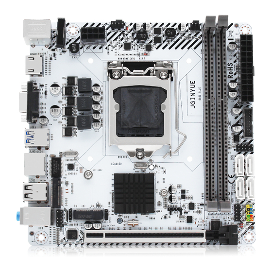
Page 4: Overview Of Components
Overview of Components Package List: B85I-PLUS Motherboard * 1 SATA cable * 1 I/O blocking * 1 — 2 —... -
Page 5: Install Cpu & Fan
Install CPU & Fan Please install the CPU into the CPU socket (LGA 1150) as shown below. Important • Make sure that the motherboard supports the CPU. • Always unplug the power cord from the power outlet before installing or removing the CPU to prevent hardware damage. -
Page 6: Install Memory
Install Memory The motherboard provides 2 DDR3 DIMM slots with a maximum capacity of 16GB. 1. Wrench the latches on both sides of the memory slot outwards. 2. Insert the memory into the slot by aligning it with the notch in the slot. 3. -
Page 7: Install Expansion Card
Install Expansion Card The motherboard provides a PCI Express 3.0 x16 expansion slot. Place the expansion card in an available PCI Express slot and press the expansion card until it is fully inserted into the slot. Important • When adding or removing expansion cards, always turn off the power supply and unplug the power supply power cable from the power outlet to prevent hardware damage. -
Page 8: Hdmi Port
HDMI Port The HDMI port supports 4K and 1080px. You can use this port to connect your HDMI-supported monitor. RJ45 LAN Port The Gigabit Ethernet LAN port provides Internet connection at up to 1000Mbps/s data rate. The following describes the states of the LAN port LEDs. Audio Port Line-in Port The line in jack. -
Page 9: Internal Connectors
Internal Connectors F_PANEL1 Connector SPEAK1 Connector JAUD1 Connector This connector allows you to connect audio jacks on the front panel. Important • An incorrect connection between the module connector and the motherboard header will make the device unable to work or even damage it. —... -
Page 10: Sata1~4: Sata 3.0 Connectors
SATA1~4: SATA 3.0 Connectors These connectors are SATA 6Gb/s interface ports. Each SATA connector supports a single SATA device. M.2 Slot Insert your M.2 SSD into the M.2 slot at a 30-degree angle. Secure the M.2 SSD in place with the scr ew. -
Page 11: Jcmos1: Cmos Discharge
JCMOS1: CMOS Discharge Important • Always turn off the computer and unplug the power cord from the power outlet before discharging. ATXPWR1, JATXPWR1: Power Connectors With the use of the power connector, the power supply can provide enough stable power to all the components on the motherboard. -
Page 12: Jusb2: Usb 2.0 Connector
CPU_FAN1, SYS_FAN1: Fan Connectors CPU_FAN is a interface for CPU radiator. The 4pin fan has PWM intelligent speed regulation function, which can intelligently control the fan speed based on load and temperature changes. SYS_FAN is the system cooling fan interface, which is generally connected to the case fan. The 3pin fan has no PWM adjustment capability. -
Page 13: Bios Setup
BIOS Setup BIOS (Basic Input and Output System) records hardware parameters of the system in the CMOS on the motherboard. BIOS identifies, configures, tests and connects computer hardware to the OS immediately after a computer is turned on. Its major functions include conducting the Power-On Self-Test (POST) during system startup, saving system parameters and loading the operating system, etc. -
Page 14: Enter Bios Setup
∙ Go to BIOS and press F6 to load optimized defaults. ∙ Short the Clear CMOS jumper on the motherboard. Important • Be sure the computer is off before clearing CMOS data. Please refer to the Clear CMOS jumper section for resetting BIOS. http://www.jginyue.com/ — 12 —...
Need help?
Do you have a question about the B85I-PLUS and is the answer not in the manual?
Questions and answers