
Summary of Contents for Devantech dS1242
- Page 1 User Manual v4.10 dS1242 dS1242 User Manual Version 4.10 Copyright © 2016-2021, Devantech Ltd. www.robot-electronics.co.uk All rights reserved.
-
Page 2: Table Of Contents
User Manual v4.10 Table of Contents Documentation history.......................... 4 A quick look............................5 Introduction............................6 Getting started............................ 7 Locating the IP Address......................8 Configuring the dS1242........................10 Status page.........................11 Network page........................12 Webpage security......................13 TCP/IP page.........................15 Configuring relays.........................16 Relay automation........................17 Relay No. box........................17 Pulse/Follow box.......................17... - Page 3 User Manual v4.10 LED indication........................55 Power supply........................55 Operating temperature......................55 Power relays........................56 Digital IO..........................57 Connection Examples......................58 Analogue inputs.......................59 Temperatue sensor......................60 Power supply input voltage....................60 Analogue channels......................60 Serial Port Connections......................61 dS1242 dimensions.......................62 Notes..............................63 Copyright © 2016-2021, Devantech Ltd. www.robot-electronics.co.uk All rights reserved.
-
Page 4: Documentation History
Webpage security settings now on Network page for compatibility with other modules. The new dSx support for dS modules which have powered RS485 ports is not applicable to dS1242, use dS2242 instead. V4.10.002 Bugfix – Timer threads operated with incorrect timing. -
Page 5: A Quick Look
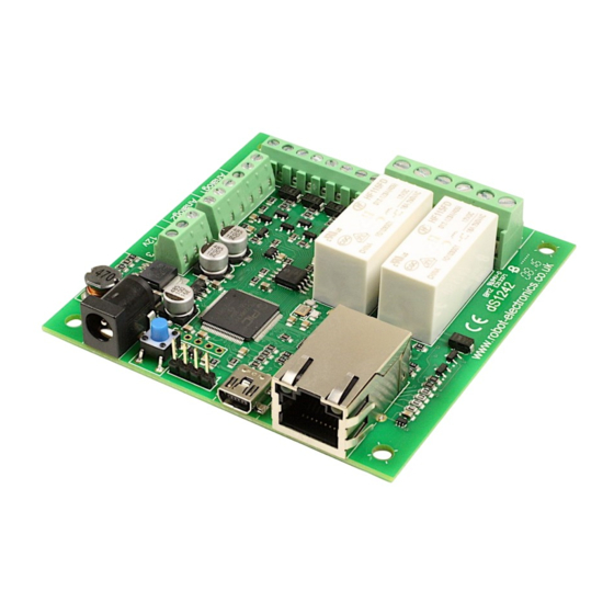
User Manual v4.10 A quick look Ethernet connected module, 10/100Mb auto negotiated. Relays – 2 x 16Amp 250Vac C/O. I/O – 4 x digital I/O's NPN output, Volt free input. 2 x 10-bit analogue input Power – 12VDC 500mA supply required. 2.1mm center positive. -
Page 6: Introduction
Each relay has both normally open (NO) and normally closed (NC) as well as the common available on three terminals. In addition to the relays, the dS1242 has 4 digital I/O channels and 2 x 10-bit analogue input channels (0v-3.3v input range). -
Page 7: Getting Started
User Manual v4.10 Getting started Start by plugging in the Ethernet cable to connect the module to your network, and the 12v jack plug from your adapter. Switch on and the first thing you will note is that the blue LED will flash 3 times. -
Page 8: Locating The Ip Address
Alternatively, you can find the IP address of the module by checking your DHCP server. If you have a DHCP server on your network (your router is normally the DHCP server) then the dS1242 will get its IP address from that. Log on to your router and navigate to the LAN client list. - Page 9 LAN. DevantechModuleFinder.jar If you do not have a DHCP server the dS1242 will use a default IP address of 192.168.0.123 so make sure your PC is on the same subnet of 255.255.255.0 and its IP address is 192.168.0.xxx...
-
Page 10: Configuring The Ds1242
User Manual v4.10 Configuring the dS1242 There are a set of configuration pages to get the dS1242 operating as you want it. These pages are all _configx.htm, (that's a leading underscore character). _config.htm _config2.htm Anything that starts with _config is considered a special name for configuration pages and can only be seen if you have the the USB cable plugged in and connected to your PC. -
Page 11: Status Page
User Manual v4.10 Status page You should now see the following page: This status page shows you the system firmware revision as well as the supplied voltage to the board and its internal temperature. If you hover your mouse cursor over the menu buttons on the left, the help panel will give you an overview of each one. -
Page 12: Network Page
User Manual v4.10 Network page Notice that everything below the Host Name is greyed out and can't be changed. This is be- cause the “Enable DHCP” box is checked and all the greyed out fields are supplied by the DHCP server. -
Page 13: Webpage Security
User Manual v4.10 Webpage security The webpage security section allows you to prevent unauthorised personnel from accessing the application webpage or using it to control the module. Leaving the Security Password blank will disable it and allow everyone to access the application page to control the module. - Page 14 User Manual v4.10 again. The default port used by html webpages is 80. You can change this if required. If you do so then you will need to include the port number in the address. If you change the port to 2345 then the webpage will be at: YourIP:2345/index.htm...
-
Page 15: Tcp/Ip Page
User Manual v4.10 TCP/IP page The TCP/IP tab allows you to select one of three command sets to control the module. These are independent of, and separate to the HTML webpage control. Clicking on one of the five check boxes will select that command set. Only one command set may be selected. -
Page 16: Configuring Relays
User Manual v4.10 Configuring relays The Relays tab allow you to set the names of the 32 relays that will be displayed on the appli- cation page. Use the Relay No. box to select the relay to configure. There are 32 relays available. Relays 1 &... -
Page 17: Relay Automation
User Manual v4.10 Relay automation If you are going to be controlling the relays from the web-page or using one of the ASCII, Bi- nary or Modbus command sets, then you do not need to do anything here. Just leave the auto- mation fields blank. - Page 18 User Manual v4.10 Here's a very simple example: Enter R2 into the Relay 1 Pulse/Follow box. This will make relay 1 copy whatever you do to Re- lay 2. Try it! Now change it to !R1. The exclamation mark is read as “Not R1”. Now relay 1 will always be the opposite of relay 2.
-
Page 19: Set Reset & Toggle Boxes
User Manual v4.10 Set Reset & Toggle boxes When used, these three controls contain boolean equations. The “Set Relay” box will set the relay when the boolean equation becomes true. The other two boxes reset and toggle the relay when the boolean equation become true. -
Page 20: Naming I/O's
User Manual v4.10 Naming I/O's The Input/Output tab is used to assign meaningful names to the I/O terminals. As with relay names these may be up to 20 characters long, but do check it looks ok on a mo- bile device or whatever you are using to control the module. -
Page 21: Pinging Remote Machines
User Manual v4.10 Pinging remote machines The ping module allows you to check other machines are still online and responding. Ping threads are only started a boot time if the Repeat Time is greater than zero. Also DNS lookup is only performed once at boot time if the Repeat Time is greater than zero. -
Page 22: Delay
User Manual v4.10 Delay This is the delay between detecting the failed responses and re-starting the pings. It is also the startup delay before beginning pings. Its purpose is to give the target machine time to boot up, or reboot. -
Page 23: Email Notifications
User Manual v4.10 Email notifications The Email tab is for sending secure, AES encrypted email notifications from the module. Up to eight (8) email notifications may be set up, selected with the Email No. box. Setting up emails is quick and easy. You just need the recipients email address, a notification message which will be the email subject line and the trigger event. -
Page 24: Peer To Peer
User Manual v4.10 Peer to Peer This tab allows you to configure events on this module to control relays on another. Up to eight (8) Peer to Peer events may be set up, selected with the P2P No. box. -
Page 25: Sequencer
User Manual v4.10 Sequencer The sequencer runs a continuous loop of up to 120 steps. At each step you can specify a time delay and the outputs. The K1 – K12 outputs are updated and the start of the delay time. The example above shows the simplest sequence possible. -
Page 26: Sequencer Commands
User Manual v4.10 Sequencer commands There are a set of 12 commands to control the sequencer. The simplest of these is just a number which is the time delay in seconds. 1234 Numbers may be up 4093 seconds. -
Page 27: K Outputs
User Manual v4.10 S1, 30 Tests S1 (Schedule 1) and jumps to line 30 if active. K Outputs The sequencer outputs are a set of 12 flags, K1 to K12. These may be used anywhere a bool- ean is used, to control relays etc. - Page 28 User Manual v4.10 Here we hold both lights at Red for 30 seconds to give traffic time to traverse the controlled area. Then Red + Amber for two seconds followed by Green for 60 seconds. We then stop the traffic with Amber for 3 seconds followed by Red.
- Page 29 User Manual v4.10 Adding a pedestrian crossing to the sequence In many sequences there are common runs of instructions. Our sequencer allows you to sepa- rate out these common sequences and call them from elsewhere in the sequence. Having only a single copy of a sequence aids in maintaining the program.
- Page 30 User Manual v4.10 Now we can modify the sequencer code. Change the 30 second delays on lines 1 and 5 and re- place them with C13. This is a call to line 13, which is on page 2. This will keep the pedestrian routine on one page for easier reading.
- Page 31 User Manual v4.10 page 1 lines 1 and 5, where we replaced them with the C13 command. We still need this delay. Line 14 tests the pedestrian request latch, relay 22, and jumps to line 16 if active, otherwise it continues with line 15 which just return to the caller on page 1.
-
Page 32: Schedules
User Manual v4.10 Schedules The scheduler can schedule regular events. These can be once or twice daily with the two start and stop times and can happen on any selected weekdays. The Schedule No. is one of eight schedules that can be set up. These are selected with the Schedule No. - Page 33 User Manual v4.10 The timezone allows you to set the time for your location. For example; GMT leave this at 0. CET set this to 1. PST set this to -8 IST set this to 5:30 Daylight saving time may be checked if required. It advances the time by 1 hour between the last Sunday in March and the last Sunday in October.
-
Page 34: Counter/Timers
User Manual v4.10 Counter/Timers Count input pulses or time events. There are a total of eight counter/timers available, selected with Counter No. box. Each counter can count at a maximum speed of 20Hz (20 counts per second). Counter Name Each counter/timer may be named and this name appears on the application page and email notifications. - Page 35 User Manual v4.10 Reset Input This input will reset the counter value to zero. If the capture Input has been left blank then it will store the current counter value in the capture register before resetting it to zero. You may use an input such as D3 or you can use the counter value itself.
- Page 36 User Manual v4.10 The internal time base, T1 is derived from the crystal on the module. It’s accurate but will drift over time so that the capture event may not happen “on the hour”. Even if you started it on the hour is will drift out by a few seconds a day.
-
Page 37: The Application Page
User Manual v4.10 The application page The last tab in the configuration pages takes you directly to the application page so you can quickly see the results of your configuration changes. The I/O indicators show grey when the I/O is inactive. -
Page 38: Application Page Security
User Manual v4.10 This application page is “index.htm” and is located in the webpage directory: /dScriptPublish-4-10/Examples/app-dS3484-v4-10/webpage/ You can use any html/javascript editor to change this file to your own requirements, such as adding a company logo or removing unused relay buttons. -
Page 39: Accessing Your Webpage From The Internet
User Manual v4.10 Accessing your webpage from the internet Now you have your webpage up and running on your local network, for example 192.168.0.150, and you can access the webpage and control the module. You just go to 192.168.0.150/index.htm, and the page is there. -
Page 40: Boolean Equations
User Manual v4.10 Boolean equations Boolean equations are used in a number of places in the configuration screens. They are used for relay automation, triggering emails and peer to peer events and the count, capture and re- set for the counter/timers. - Page 41 User Manual v4.10 To demonstrate a real world example, take the analog example above where we compared A1 with 1000 to operate R2. Whilst this would work its a not a good solution as the relay would jitter badly when A1 was hovering between 999 and 1000. What we need is some hysteresis.
-
Page 42: Tcp/Ip Command Sets
User Manual v4.10 TCP/IP command sets There are four TCP/IP command sets on four selectable check boxes, of which one or none may be selected on the TCP/IP config tab. These are ASCII, Modbus, Binary and Binary with AES256 encryption. - Page 43 User Manual v4.10 Valid commands are: STatus request SR [Relay number] [on/off] {Pulse time in mS} SR 1 on Set Relay 1 on SR 1 off Set Relay 1 off SR 1 on 1000 Set Relay 1 on for 1 second...
-
Page 44: Binary Command Set
Update all Relays 0x30 (decimal 48) Get Status (1 byte command, returning 8 bytes) This command returns 8 bytes of status data Module ID This will be 31 (0x1F) for the dS1242 System Firmware Major 2 for example System Firmware Minor... - Page 45 User Manual v4.10 0x32 0x04 0x01 Set Output (3 byte command, returning 1 byte) This command turns an output on or off and returns an ACK/NACK byte. ACK=0, NACK=non- zero (actually the unknown I/O port number). All I/O's which need to be inputs should have the output turned off. When turned on the NPN transistor can sink up to 100mA.
- Page 46 User Manual v4.10 Binary Command Set – continued. 0x35 Get Analogue inputs (1 byte command returning 4 bytes) This returns all 2 possible analogue inputs. 4 bytes are returned, 2 for each analogue input. Byte 1 byte 2...
-
Page 47: Aes Binary Command Set
User Manual v4.10 AES binary command set The AES Binary commands are the same as the Binary commands described above. The only difference is that they are AES encrypted and always 16 bytes in length. The first bytes are the same as described in the Binary command set. - Page 48 User Manual v4.10 The following example shows how the Nounce provided by the module is used in the next Set Relay or Set Ouput command. Get Status 0x30 Response 0x1F 0x02 0x12 0x01 0x02 0x7D 0x01 0x0B 0x89...
-
Page 49: Modbus Commands
User Manual v4.10 Modbus commands The modbus command set accepts a subset of the standard Modbus-TCP frames as defined in Modbus protocol Specification MODBUS Messaging on TCP/IP Implementation Guide V1.0b Functions 1, 4, 5 & 15 are supported along with error codes 1, 2 & 3 should they occur. -
Page 50: Function 05 (0X05) Write Single Coil
User Manual v4.10 Function 05 (0x05) Write Single Coil This function is used to write to a single coil (relay or I/O). Coils 1-2 are the relays 1-2. Coils 41-44 are the I/O's 1-4 remapped to coils 41-44. -
Page 51: Loading The Application Firmware
In this order: 1. Start from this position: a. dScript Editor closed down. b. dS1242 not connected or powered. 2. Power-up the dS1242. 3. Hold down the reset button for a couple of seconds until the red LED comes on. This in- dicates the module is in boot-loader mode. - Page 52 User Manual v4.10 5. Run the dScript editor. Look in Help About and check you have the latest version of → dScript. In this case 4.10 If you have an earlier version you should uninstall it and install the new version from the installation folder, then start these instructions from the beginning.
-
Page 53: Erasing Old Configuration Settings
Load up the app-dS1242-v4-10 application in the editor, but before you upload it to the dS1242 you need to make a small change. Locate the thread "main" (click the word in the right panel is quickest). Just below this is a commented out line "init()". -
Page 54: Ds1242 Hardware
User Manual v4.10 dS1242 Hardware The dS1242 provides two (2) volt free contact relay outputs with a current rating of up to 16Amp each, 4 digital I/O's which can be an NPN transistor output or accept a volt free input (from relay or switch contacts, etc). -
Page 55: Led Indication
The “FlashingLeds” example provides a colourful display showing how to use them. Power supply The dS1242 requires a 12v DC supply capable of supplying a minimum of 500mA. This is most easily provided by a low cost mains adapter. A suitable universal adapter is available on our website and may be ordered along with the modules. -
Page 56: Power Relays
The relay coil is powered by the 12vdc incom- ing supply on user command. Coil Relay in passive state Coil Relay in powered state A full datasheet for the relays used on the dS1242 is here: HF115FD datasheet Copyright © 2016-2021, Devantech Ltd. www.robot-electronics.co.uk... -
Page 57: Digital Io
Our Ethernet modules could potentially have many types of outputs. For example the ETH008 only has one type - Relays. The dS1242 has both Relay outputs and NPN Open Collector Tran- sistor outputs. Activating a relay means turning the relay on. Likewise activating an output means turning the transistor on. -
Page 58: Connection Examples
User Manual v4.10 Connection Examples Example input - connecting a switch Connecting a simple switch could not be easier, just wire the switch be- tween a pin (P) and ground (G). When the switch closes the input will become active. -
Page 59: Analogue Inputs
User Manual v4.10 Analogue inputs Two independent analogue input channels of 10-bit resolution are provided for sampling volt- ages up to 3.3V. Each channel is also filtered with a 10k resistor and a 100n capacitor to sta- bilise high frequency jitter, there is also a pull down resistor so the port will read around 0 when nothing is connected. -
Page 60: Temperatue Sensor
User Manual v4.10 Temperatue sensor There is an on-board temperature sensor (MCP9700A) which provides a 10mV/°C output on a 500mV offset (0°C = 500mV, 1°C = 510mV). This is accessed as analogue channel 100. The sensor is located between the Ethernet connector and the edge of the PCB just above the mounting hole. -
Page 61: Serial Port Connections
User Manual v4.10 Serial Port Connections TTL serial ports. The dS1242 has one serial port header. Pin 1 is marked on the PCB. Tx and Rx operates at 3.3v levels, however the Rx input is 5v tolerant. Most 5v TTL level serial ports will accept a full 3.3v input ensur-... -
Page 62: Ds1242 Dimensions
User Manual v4.10 dS1242 dimensions Copyright © 2016-2021, Devantech Ltd. www.robot-electronics.co.uk All rights reserved. -
Page 63: Notes
User Manual v4.10 Notes Copyright © 2016-2021, Devantech Ltd. www.robot-electronics.co.uk All rights reserved.
Need help?
Do you have a question about the dS1242 and is the answer not in the manual?
Questions and answers