Table of Contents
Advertisement
Advertisement
Table of Contents

Summary of Contents for imes-icore iVAC eco+
- Page 1 iVAC eco+ DUST EXTRACTION UNIT Version 1 Aug 2012...
-
Page 2: Table Of Contents
TABLE OF CONTENTS SAFETY INSTRUCTIONS ..................... 3 Symbols used ........................ 3 Electrical safety......................3 Dangers to eyes, breathing and skin ................3 Warning and Information Labels .................. 4 INSTALLATION ......................... 5 Extractor Overview ....................... 5 Extractor Installation Procedure ................... 6 Feature Considerations .................... -
Page 3: Safety Instructions
SAFETY INSTRUCTIONS Symbols used Danger 'Risk of Electric Shock' Refers to an immediately impending danger. If the danger is not avoided, it could result in death or severe (crippling) injury. Please consult the manual where this symbol is displayed. Warning Refers to a possibly dangerous situation. -
Page 4: Warning And Information Labels
Warning and Information Labels Label/Symbol Position Inside Filter Door (at top) Top Left of rear panel Rear of unit, next to power connection Above motor cooling on rear of unit Top Left of Front Door Version 1 Aug 2012... -
Page 5: Installation
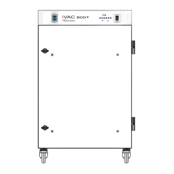
INSTALLATION Extractor Overview This unit provides extraction and filtration of the fume generated by marking, milling, cutting, etching or engraving. The units are of robust design and feature ease of use with minimal maintenance. The main components are shown in Fig. 1. Fig. -
Page 6: Extractor Installation Procedure
Extractor Installation Procedure Caution If this equipment is used in a manner not specified by the manufacturer, the protection provided by the equipment may be impaired. Read all instructions in this manual before using this extractor. 1. Move the unit to the location where it is going to be installed and remove the unit from its packaging. -
Page 7: Filter Blocked Signal
Filter blocked signal With this, the extraction unit has been fitted with a pressure switch to monitor the condition of the filters. This is displayed via the Red LED on the front of the unit. This circuit will not directly stop the extractor motor. Remote stop/start This enables the extractor unit to be turned on and off by a signal from the customer. -
Page 8: General Safety Requirements
Caution: Check that the mains input at the isolated supply is the same as the voltage Supply detail on the Serial Number label before plugging the extractor unit in. General Safety Requirements Caution Do not block or cover the cooling vents on the unit, as this severely restricts airflow and may cause damage to the unit. -
Page 9: Operation
OPERATION Manual operation The extraction unit is turned off and on by means of an illuminated rocker switch on the front of the unit. Manual Auto Extraction Filter condition signal – indicators & component controls. The LED on the front panel (see above Fig) indicate when the filter is blocked. The right switch will allow the vacuum motor to be either On/Off/Auto. -
Page 10: Maintenance
Maintenance General User maintenance is limited to cleaning the unit and replacing the filters with new. Only imes-icore trained maintenance technicians are authorised to carry out component testing and replacement. Unauthorised work or the use of unauthorised replacement filters may result in a potentially dangerous situation and/or damage to the extractor unit, and will invalidate the manufacturer’s warranty. -
Page 11: Pre Filter Replacement
Pre filter replacement The pre filter needs changing when the filter change is illuminated. Isolate the electrical supply to the extractor. 1. Undo the filter compartment latches on the front of the unit. 2. Remove the pre filter by lowering the supporting plate and replace with a new pre filter. -
Page 12: Maintenance Protocol
Maintenance Protocol Filters to be changed in accordance with instructions. Log the date of filters changed in the table below: Unit Serial Number Pre Filter Date Name Filter Disposal Pre filters are manufactured from non-toxic materials. Filters are not re-usable, cleaning used filters is not recommended. Disposal of the used filters depends on the material deposited on them. -
Page 13: Trouble Shooting
TROUBLE SHOOTING In the unlikely event of a problem with your extractor please contact your local representative. imes-icore GmbH Im Leibolzgraben 16 D-36132 Eiterfeld Tel: +49 (0)6672/898-228 Fax: +49 (0)6672/898-222 Email: info@imes-icore.de Website: www.imes-icore.de Version 1 Aug 2012... -
Page 14: System Specifications
SYSTEM SPECIFICATIONS Unit: iVAC eco+ Capacity: 260 m³/hr Size: Height 750mm x Depth 460mm x Width 440mm Weight: 30Kg Exhauster: Centrifugal Blower Electrical supply: 115-230v 1ph 50/60Hz FLC: 12.5A Noise level: Below 75dB (A) Filters: Pre filter Efficiency F8 95% @ 0.9µ Environmental Operating Range Temperature +5°C to +40°C...
Need help?
Do you have a question about the iVAC eco+ and is the answer not in the manual?
Questions and answers