
Summary of Contents for RFbeam Microwave ST200
- Page 1 ST200 Radar Evaluation System User Manual © RFbeam Microwave GmbH www.rfbeam.ch January 2013 Page 1/27...
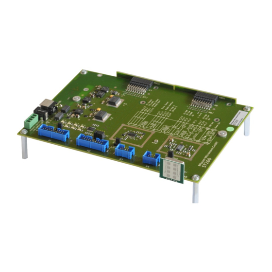
- Page 2 Learning and Exploring Radar Basics Description ST200 is a 16Bit data acquisition and processing system with a total 250k/s sampling rate. It contains all hardware necessary for acquiring Radar signals of RFbeam Transceivers. ST200 contains a motherboard with power supply, amplifiers and I/O connectors. Data acquisition is performed by a NI-USB-6211 16Bit multifunction DAQ module from National Instruments mounted on the backside.
-
Page 3: Getting Started
• PC running on Windows xp or never • Installing Signal Explorer Software ST200 software comes with a setup procedure containing all necessary components into one single package: RFbeam ST200 Signal Explorer Software • National Instruments DAQmx ® driver software •... - Page 4 Fig. 1 1. Plug in a K-LC2 radar sensor into connector X5 of the ST200. 2. Connect ST200 hardware to you computer. There should appear a “New USB Hardware Found” message from Windows. 3. Windows will probably ask you for a hardware driver. Select to find it aoutomatically.
- Page 5 User Manual ST200 Evaluation System ST200 Hardware ST200 consists of a mother board and a 16 Bit USB data acquisition system with 250kHz sampling rate. The mother board contains 5V and 3.3V low noise power supplies and analog buffers and amplifiers.
-
Page 6: Typical Sensor Connections
Sensors with higher current consumption (>120mA like K-MC4) need more power than USB can deliver. An external DC 12V power supply with >0.5A should be plugged into X10 of the ST200 system. K-LCx Series → X5 or X4 Sensors of the K-LCx series with no internal amplifiers can directly be plugged into X5. -
Page 7: Getting Help
Select Help - Show ContextHelp from main menu. This opens a floating window containing a brief description of the object pointed by the mouse cursor. Operation Modes ST200 Signal Explorer provides 3 main operation modes: Doppler Mode: Speed and direction measurements •... -
Page 8: Operation Section
Recorder Section ST200 Signal Explorer allows real time recording and playback of signals captured in the Doppler and in the FSK mode. © RFbeam Microwave GmbH www.rfbeam.ch... - Page 9 This can be accomplished by measuring the Radar sensor distance with the radar sensor (e.g. using FSK technology) or by measuring the angle using a monopulse radar such as Fig. 6: Definition of angle α K-MC4. © RFbeam Microwave GmbH www.rfbeam.ch January, 2013 Page 9/27...
- Page 10 Fig. 7: Logarithmic FFT scale Note the difference: in linear mode, small signals and noise disappear. Linear display Fig. 8: Linear FFT scale Remember to reset cursors after switching between logarithmic and linear mode. © RFbeam Microwave GmbH www.rfbeam.ch January, 2013 Page 10/27...
- Page 11 ST200 Evaluation System Chart Modes Besides the classical scope modes, ST200 allows “chart” modes for viewing slow signals. Zooming and shifting charts Data for the charts come from the signal buffer. Scaling is performed on display level and not on signal level.
- Page 12 RMS amplitude chart of a selected peak. The amplitude drops to 0, as soon as the peak in the FFT falls outside the selected area. In our example, it dropped under the minimum level selected by the horizontal cursor. © RFbeam Microwave GmbH www.rfbeam.ch January, 2013 Page 12/27...
- Page 13 Fig. 12: Display I and Q phase relation to evaluate moving direction Complex FFT receding targets approaching targets Time signal display Fig. 13: Complex FFT with one approaching target: peak on right side © RFbeam Microwave GmbH www.rfbeam.ch January, 2013 Page 13/27...
- Page 14 Above: Stationary object, Below: Moving object Distance can be calculated as follows: For legend refer to Fig. 14 above ⋅ ⋅T Range, distance to target Speed of light (3 * 10 m/s) © RFbeam Microwave GmbH www.rfbeam.ch January, 2013 Page 14/27...
- Page 15 IF amplifiers are less stressed than with sawtooth modulation • Advanced FMCW Modulation Techniques Triangle modulation may be extended with phase of constant frequency to allow Doppler detection. You find examples in chapter Exploring FMCW. © RFbeam Microwave GmbH www.rfbeam.ch January, 2013 Page 15/27...
- Page 16 Similar effects may be caused by poor quality of the cover in front of the sensor antenna. The cover is often called RADOM (from Radar Dome). The reason is different reflectivity at different frequencies. Please contact RFbeam for more informations on Radom. © RFbeam Microwave GmbH www.rfbeam.ch January, 2013 Page 16/27...
- Page 17 VCO Linearization ON/OFF VCO Linearization Tool Fig. 17: ST200 FMCW Screen Overview using a K-MC1 sensor. Bottom right graph in Fig. 17 demonstrates a calculated VCO ramp (yellow) to get a linear frequency ramp (blue). For more details on linearization refer to chapter FM Linearization.
-
Page 18: Fsk Mode
• bandwidth limitations FSK has the advantage of simple modulation and does not suffer from linearity problems • VCO signal generation is simple, but sampling and phase measurement is challenging • © RFbeam Microwave GmbH www.rfbeam.ch January, 2013 Page 18/27... - Page 19 Please note, that FSK allows even moving direction detection with the 1 channel K-LC1. Technical Background ST200 generates a continuous rectangular signal stream at the VCO input of the Radar sensor. With a strict and jitter free clock, two signal buffers, one for f...
-
Page 20: Recording And Playback
Fig. 22: 4 files limited to 10MB each Fig. 23: Resulting files in Multi File mode selected as in Fig. 22 Please find more details on TDMS file format on http://zone.ni.com/devzone/cda/tut/p/id/3727. © RFbeam Microwave GmbH www.rfbeam.ch January, 2013 Page 20/27... - Page 21 User Manual ST200 Evaluation System Settings Configurations ST200 settings including sensor type are collected in configurations. You may generate as many configurations as you need. Configurations Setup You may alter or copy existing configurations. New configurations may be generated. Select predefined configurations from list box.
- Page 22 You may define new sensors by copying an existing file and editing by an ASCII editor like notepad or similar. VCO values must be known and can be evaluated by using RFbeam K-TS1 test system (http://rfbeam.ch/fileadmin/downloads/datasheets/Datasheet_K-TS1.pdf) © RFbeam Microwave GmbH www.rfbeam.ch January, 2013 Page 22/27...
- Page 23 • FM Linearization ST200 provides a tool "VCO-Lin" for interpolating the VCO characteristic from 3 known points. Output may be exported as csv file and can be used as table for your own FMCW system. Call the tool by the [Set VCO] button in FMCW mode (see Fig.
- Page 24 ***.ini will be copied to user space during installation Note 1) : AI_Config.ini contains hardware informations on the ST200 platform Working Files During installation, setup procedure copies the files below to user directories. Location depends on operating system. These files should not be changed directly, but are affected by the different setup options of Signal Explorer.
- Page 25 Configure with JP2 to DI2 or DO2 DIO3 Digital Input or Output Configure with JP2 to DI3 or DO3 AI12 Analog Input direct to AI12 Range of ±0.2V, ±1V, ±5V, ±10V +5V, 400mA max © RFbeam Microwave GmbH www.rfbeam.ch January, 2013 Page 25/27...
- Page 26 1 channel modules Supply configurable with JP4 +3.3V/0.4A or +5V/0.4A IF_I Doppler Signal I (in phase) used by single channel modules -0.5 … 2V Output Limited and buffered from AO0 Not Connected © RFbeam Microwave GmbH www.rfbeam.ch January, 2013 Page 26/27...
-
Page 27: Document Revision History
40dB not used in SignalExplorer Software X10 Optional DC Power In This input must be used, if USB does not deliver enough current to power ST200 including connected modules. X11 Power Out The power out connector X11 can be used to supply external devices with low noise supply voltages.
Need help?
Do you have a question about the ST200 and is the answer not in the manual?
Questions and answers