Table of Contents
Advertisement
Quick Links
Advertisement
Table of Contents

Summary of Contents for Portwell PCS-8279
- Page 1 PCS-8279 In-Vehicle Computing User's Manual Document No. Document Name PCS-8279 User Manual UM021341001 Date Version Feb. 2013 Reversion History : Reversion Date Author(s) Notes From Feb. 2013 Initial document issued APT Editors...
- Page 2 Other brands and product names used herein are for identification purposes only and may be trademarks of their respective owners. Disclaimer PORTWELL® Technology Corp. shall not be liable for any incidental or consequential damages resulting from the performance or use of this product. PORTWELL®...
- Page 3 Safety Information Read the following precautions before setting up a PORTWELL Product. Electrical safety • To prevent electrical shock hazard, disconnect the power cable from the electrical outlet before relocating the system. • When adding or removing devices to or from the system, ensure that the power cables for the devices are unplugged before the signal cables are connected.
-
Page 4: Table Of Contents
TABLE OF CONTENTS 1 Function Introduction Model Specifications..................6 PCS-8279 Illustration <Mainboard, System>..........8 Memory Module Installation .................10 Architecture ....................11 Principal Component Specification ..............12 Internal Connector Specification ..............13 ■ VGA Connector ...................13 ■ USB Connector ...................14 ■ GPIO Connector ..................16 ■ UART and GPIO Connector ................17 ■... - Page 5 3 BIOS 3.1 Entering The BIOS ..................46 3.2 Main........................48 3.3 Advanced .......................49 3.4 Boot ........................55 3.5 Security ......................56 3.6 Chipset ......................57 3.7 Exit .........................59 4 Packing List Packing List ....................60...
-
Page 6: Function Introduction
1 Function Introduction 1.1 Model Specifications • Intel Cedarview Atom D2550 Dual Core 1.8GHz Processor • Intel NM10 Chipset • 1 x DDR3 1066MHz SO-DIMM up to 4GB Memory • Intel GMA3650 Graphics • 2 x Serial ATA 2.0 Ports •... - Page 7 • 4 x SMA-type External Antenna Connectors for WLAN / UMTS / GSM / Antenna GPRS / GPS / Bluetooth • 1 x 2.5" drive bay for SATA Type Hard Disk Drive / SSD Storage • 1 x SATA DOM •...
-
Page 8: Pcs-8279 Illustration
1.2 PCS-8279 Illustration Mainboard... - Page 9 System...
-
Page 10: Memory Module Installation
1.3 Memory Module Installation The PCS-8279 has one 204-pins SODIMM slot for DDR3 1066MHz SDRAM memory modules and supports memory up to 4GB. These DIMM slots are intended for memory modules. DDR3 SO-DIMM Slot 204-pin, 1.5V Installing Memory Module 1. Locate the DIMM1 SO-DIMM slot. Align the notch on the DIMM with the key on the slot and insert the DIMM into the slot at 45-degree angle. -
Page 11: Architecture
1.4 Architecture... -
Page 12: Principal Component Specification
1.5 Principal Component Specification # of Cores # of Threads Clock Speed 1.86 GHz L2 Cache 1 MB Instruction Set 64-bit Lithography 32 nm Max TDP 10 W VID Voltage Range 0.91V -1.21V TJUNCTION 100 C Package Size 22mm X 22 mm Sockets Supported FCBGA559 Integrated Graphics... -
Page 13: Internal Connector Specification
1.6 Internal connector specification... -
Page 16: Gpio Connector
Englsh... -
Page 17: Uart And Gpio Connector
Engl... -
Page 31: External Connector Specification
1.7 External connector specification... -
Page 36: Ignition Power Management Quick Guide
1.8 Power Ignition Management Quick Guide Startup/shutdown conditions from the IGNITION signal: 1. IGNITION startup signal must be valid for 10 sec. (This is a protection mechanism against power-noise generated inside the vehicle.). 2. IGNITION shutdown – IGNITION signal must be inactive for 5 minutes, then PIC controller shall initiate Power Button off signal to turn off the system. - Page 37 4. If the vehicle ignition is turned on, while the power-off delay is in progress, PCS- 8279 will cancel the power-off delay function, and continue to operate normally. 5. If the vehicle ignition is turned-on, while the power-off delay duration is ended, PCS-8279 will shut- down completely first, then power-on automatically.
-
Page 38: System Installations
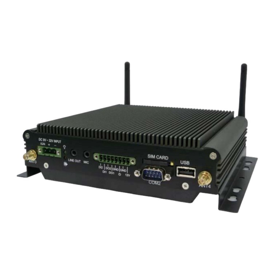
2 System Installation 2.1 System Introduction DC In Power LED Mic In Digital I/O SIM Card USB2.0 Port Line Out GPS Antenna 3 3G Antenna 4 COM2 Port HDD/SSD LED LAN Port USB2.0 Port COM1 Port WIFI / BT Antenna 2 WIFI/BT Antenna 1... -
Page 39: Opening Chassis
2.2 Opening Chassis Step 1. Unscrew the four screws of the Back Cover as shown in the picture. Step 2. Unscrew the four screws of Rear/Front Panel as shown in the picture. Step 3. Open the Back Cover as shown in the picture. -
Page 40: Installing Memory
2.3 Installing Memory Step 1. Put Memory on this place as shown in the picture. Step 2. Hold the Memory with its notch aligned with the Memory socket of the board and insert it at a 30-degree angle into the socket as shown in the picture. -
Page 41: Installing Hdd / Ssd
2.4 Installing HDD / SSD Step 1. Put the HDD on the Back Cover as shown in the picture. Step 2. Turn over the Back Cover and screw the four screws of the Back Cover as shown in the picture. Step 3. -
Page 42: Installing Mini Pci Express Expansion Card
2.5 Installing MINI PCI Express Expansion Card Step 1. Put MINI PCIe Expansion Card on this place as shown in the picture. Step 2. Hold the Module with its notch aligned with the socket of the board and insert it at a 30 degree angle into the socket as shown in the picture. -
Page 43: Installing Mini Pci Express Expansion Card
Installing MINI PCI Express Expansion Card Step 1. Put MINI PCIe Expansion Card on this place as shown in the picture. Step 2. Hold the Module with its notch aligned with the socket of the board and insert it at a 30 degree angle into the socket as shown in the picture. -
Page 44: Installing Sim Card
Step 1. Use thin stick to push the button as shown in the picture. Step 2. Take the holder away from PCS-8279 as shown in the picture. Step 3. Put your SIM Card into the holder as shown in the picture. -
Page 45: Installing Battery Module
2.8 Installing Battery Module Step 1. Apply two screws on the back cover as shown in the picture. Step 2. Connect the Cable to UPS1 Connector as shown in the picture. -
Page 46: Bios
• Upon boot-up, the 1st line appearing after the memory count is the BIOS version. It is usually in the format. PCS-8279 Mainboard V1.0 073109 where : 1st digit refers to BIOS maker as A = AMI, W = AWARD, and P = PHOENIX 2nd - 5th digit refers to the model number. - Page 47 Control Keys Power on the computer and the system will start POST (Power On Self Test) process. When the message below appears on the screen, press (DEL) key to enter Setup. <↑> Move to the previous item <↓> Move to the next item <←>...
-
Page 48: Main
3.2 Main System Time This setting allows you to set the system time. The time format is <Hour> <Minute> <Second>. System Date This setting allows you to set the system Date. The time format is <Day> <Month> <Date> <Year>. -
Page 49: Advanced
3.3 Advanced CPU Configuration... - Page 50 » Max CPUID Value Limit The Max CPUID Value Limit BIOS feature allows you to circumvent problems with older operating systems that do not support the Intel Pentium 4 processor with Hyper-Threading Technology. When enabled, the processor will limit the maximum CPUID input value to 03h when queried, even if the processor supports a higher CPUID input value.
- Page 51 PCI/ PCIE Device Configuration...
- Page 52 Super IO Configuration » Serial Port 0/1/2/3/4/5 Enable or Disable Select an Enable or Disable for the specified serial ports. » Serial Port 0 Mode The settings specify the RS-232/RS-422/RS-485 mode of the serial prot 0.
- Page 53 Hardware Health Configuration These items display the current status of all monitored hardware devices/components such as voltages, temperatures and all fans' speeds.
- Page 54 GPIO Configuration » GPO 0/ 1/ 2/ 3/ Data These settings configure special GPIO data. Power off Delay Time Setting...
-
Page 55: Boot
3.4 Boot » 1st/2nd/3rd Boot Device The items allow you to set the sequence of boot devices where BIOS attempts to load the disk operating system. » Try Other Boot Devices Setting the option to [Enabled] allows the system to try to boot from other device if the system fail to boot from the 1st/2nd/3rd boot device. -
Page 56: Security
3.5 Security » Administrator Password Administrator Password controls access to the BIOS Setup utility. These settings allow you to set or change the administrator password. » User Password User Password controls access to the system at boot. These settings allow you to set or change the user password. -
Page 57: Chipset
3.6 Chipset... - Page 58 » Select Graphic Output Mode...
-
Page 59: Exit
3.7 Exit » Save Changes and Exit Save changes to CMOS and exit the Setup Utility. » Discard Changes and Exit Abandon all changes and exit the Setup Utility. » Discard Changes Abandon all changes and continue with the Setup Utility. »... -
Page 60: Packing List
4.1 Packing List Item Description System PCS-8279 main system Power terminal PHOENIX CON MALE 3PIN GPIO terminal PHOENIX CON MALE 8PIN...
Need help?
Do you have a question about the PCS-8279 and is the answer not in the manual?
Questions and answers