Table of Contents
Advertisement
Quick Links
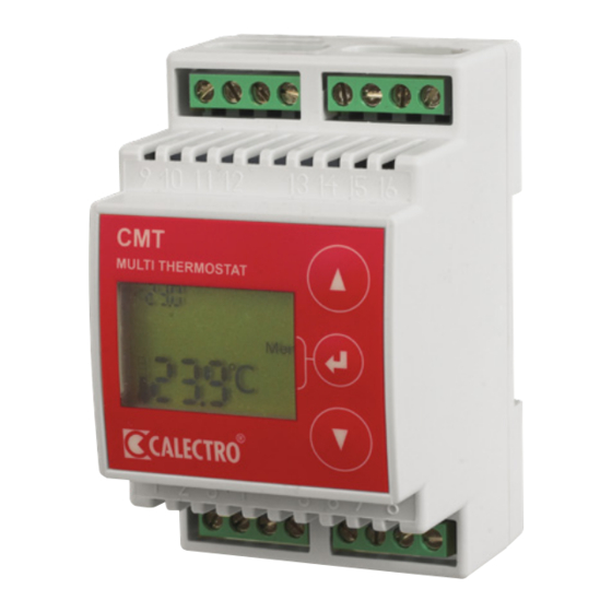
CMT-24/230V INSTALLATION INSTRUCTIONS
ENGLISH
Universal thermostat with 11 built-in and
selectable functions.
Multi-voltage: 24V AC/DC and 230V AC.
WARNING: IMPORTANT
INFORMATION
!
CONCERNING
ELECTRICAL SAFETY
AND ENVIRONMENT
The product may incorporate lethal volt-
age. The product's enclosure is not intend-
ed to be opened. At 230V AC supply volt-
age the product shall be powered via a
proximally mounted disconnection device
marked: "Disconnection device for ther-
mostat CMT". The product's relay switch
can be energised with 230V which must
be disconnected prior to conducting main-
tenance work. The product is intended for
indoor use. The product shall not be sub-
jected to liquids or moisture. The outside of
the product can be cleaned using a slightly
moist cloth rag. The product is intended for
installation on a DIN rail / Norm enclosure
in an area protected from the public.
INDEX
1.
Technical data
3. Use
4.
Installation
5. Maintenance
6. Buttons and menu system
7.
Selection of application/function
8. Selection of temperature sensor type - fac-
tory setting: Pt1000
9.
11. Fine-adjustment of the temperature meas-
urement
17. Connection example for each respective
application
Calectro AB Phone: +46 31-69 53 00 info@calectro.com www.calectro.com
1.
TECHNICAL DATA
Supply voltage:
24V AC ±10%,
24V DC ±5% and
230V AC ±10% 50-60 Hz
Relay outputs:
250V ~ 5A resistive
loading, change-over
potential-free
Power consumption: 4W
Temperature range:
-99 to +600°C
Ambient temperature: 0 to +40°C
Selectable
temp.sensors:
Pt1000 (factory setting),
Pt100, Ni1000,
NTC (Calectro type:
22/33/44/55/99) and
PTC (Calectro type: 95)
Switching differential: 0-15°C in stages of 0.2°C
Mounting:
DIN rail, Norm-enclosure
Dimensions WxHxD: 52.5 x 86 x 59mm
Weight:
240 g.
Enclosure class:
IP20
2. FUNCTION
CMT can be powered by 24V AC/DC via plinth 15-16
or 230V AC via plinth 1-2. See figure 2. CMT has two
alternating potential-free relay outputs (5 A, 250V)
and has an adjustable hysteresis (switching differen-
tial) which is centred over the reference value.
CMT carries out a self-test during start-up and fol-
lowing change of temperature sensor. Three bars
blink at the lower part of the display. Once the self-
test has finished the actual temperature will be dis-
played. In the case of interruption to the temperature
sensor the display shows Er0 and in the case of
short-circuit Er1 is displayed.
3. USE
Universal thermostat with 11 built-in and selectable
functions:
Appl. 1
1-stage heating thermostat
Appl. 2
1-stage cooling thermostat
Appl. 3
2-stage heating thermostat
Appl. 4
2-stage cooling thermostat
Appl. 5
2-stage heating and cooling thermostat
Appl. 6
1-stage cooling thermostat with low tem-
perature alarm
Appl. 7
1-stage heating thermostat with overheat-
ing alarm
Appl. 8
2-stage overheating alarm
Appl. 9
High and low temperature alarm
Appl. 10 Gutter thermostat, relay 2 = fault alarm
Appl. 11 Gutter thermostat with whole numbers,
relay 2 = fault alarm
4. INSTALLATION
CMT is mounted on a DIN rail and is adapted to Norm
enclosures.
Gutter thermostat (application 10 and 11)
Positioning of thermostat and outdoor temperature
sensor.
In order to counteract icing heated cables are used in
guttering and downpipes. The temperature at which
ice forms varies from building to building depending
on several factors such as, on the degree of insula-
tion, the compass direction, radiated heat from the
Sun, etc. Position the thermostat in an easily acces-
sible position for service personnel inside the build-
ing. The outside temperature sensor is positioned on
the building's north elevation in a position away from
direct sunlight, e.g. under the soffit See figure 3.
EN
5. MAINTENANCE
CMT is maintenance-free.
6. BUTTONS AND MENU SYSTEM
▲ = Step up in the menu / increase value - Keep
the button depressed and the reference value
counts up rapidly.
▼ = Step down in the menu / decrease value -
Keep the button depressed and the reference
value counts down rapidly.
= Is a multi-function button whose current
function* is shown in the display beside the button.
* Central button functions:
• Exit Menu = Exit the menu/Save setting
• Menu Enter = Enter submenu
• Menu = Enter the menu or select application
• Enter = Confirm setting
• Reset = To reset relay after alarm, applica-
tions 6-9
Exit
Menu
Enter
Reset
The menu system consists of the following sub-
menus:
1. Selection of temperature sensor
2. Setting of hysteresis
3. Fine-adjustment of the temperature meas-
urement
4. Timer functions
5. End the menu system
7.
SELECTION OF APPLICATION/
FUNCTION
CMT is a multi-functional thermostat with eleven
selectable applications:
To select an application the central button must
be in function: "Menu". Press
depressed. Then press ▲ and keep both but-
tons depressed for 4 seconds. APP will now be
displayed in the upper left-hand corner with the
relevant application number. On the one side of
the thermostat there is an application overview.
Mark the sticker with the application setting for
future service and maintenance.
desired application with ▲ and ▼ then confirm
with Enter (
).
Enter
and keep it
Choose the
Advertisement
Table of Contents

Subscribe to Our Youtube Channel
Summary of Contents for CALECTRO CMT-24/230V
- Page 1 18. Menu system – overview/quick menu ing. The outside temperature sensor is positioned on the building's north elevation in a position away from direct sunlight, e.g. under the soffit See figure 3. Calectro AB Phone: +46 31-69 53 00 info@calectro.com www.calectro.com...
- Page 2 Pt100, Pt1000, Ni1000 3. Press Menu-Enter to change hysteresis. and the ETF series for Calectro's NTC and PTC Set point value for relay 2 is displayed in the upper 4. The actual hysteresis now starts to flash sensors.
- Page 3 = cooling activated 22/33/44/55/99) 40°C 6539 in the CMT can be adjusted. Range: -3.0°C to 0°C 1631 +3.0°C in steps of 0.1°C. Calectro type 95) 20°C 1915 < > 1. Press the Menu button ( ) to access the 40°C...
- Page 4 17. CONNECTION EXAMPLES FOR EACH RESPECTIVE Application 6: 1-stage cooling with interlocked alarm relay APPLICATION Relay 1 Relay 2 NC C NO NO C NC Relays are shown in a currentless condition Relay 1 Relay 2 Supply to load Application 1: 1-stage heating Application 7: 1-stage heating with interlocked alarm relay Relay 1 Relay 1...
- Page 5 18. MENU SYSTEM - OVERVIEW Press Menu to access the Menu System. Navigate between the submenus using the arrow keys and select sub-menu with Menu-Enter. < > Menu ° Select the type of temperature sensor. Navigate between the different types and confirm with Enter. Pt1000 Menu Pt1000...
Need help?
Do you have a question about the CMT-24/230V and is the answer not in the manual?
Questions and answers