Table of Contents
Advertisement
Advertisement
Chapters
Table of Contents

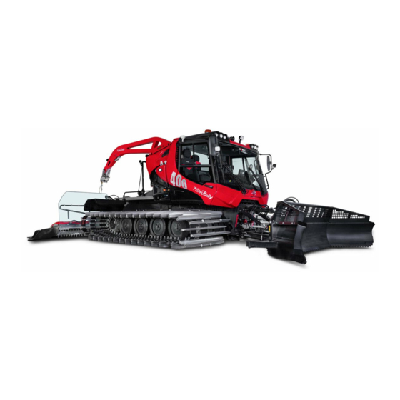
Summary of Contents for Kässbohrer PistenBully 400 4F
- Page 1 Operating Manual Vehicle From WKU 824 11319.en...
- Page 2 Kässbohrer Geländefahrzeug AG Kässbohrerstraße 11 D-88471 Laupheim Printed in Germany Copyright ® Not to be reprinted, translated or duplicated either wholly or in part without written permission. Technical details might not necessarily be exactly as described or illustrated in this operating manual.
-
Page 3: Table Of Contents
ONTENTS NTRODUCTION Cockpit......34 Technical Customer Service and PistenBully transport ....91 Replacement Parts Sales . - Page 4 ONTENTS UXILIARY EQUIPMENT THER ON BOARD DOCUMENTS Front blade..... 151 – Operating manual: maintenance instructions – Logbook AlpinFlex tiller ....154 –...
-
Page 5: Introduction
NTRODUCTION Your experience is important to us! Use of genuine spare parts We recommend using original parts from Kässbohrer We strive relentlessly to create a complete and correct docu- Geländefahrzeug AG and conversion and accessory parts that mentation for your product. However, we very much appreciate have been expressly approved for your vehicle type. - Page 6 NTRODUCTION TO THE OPERATING MANUAL Symbols used This operating manual provides: Information on how to handle, maintain and care for your DANGER! PistenBully. There is an immediate danger to life and limb Important instructions concerning correct and economical ...
- Page 7 EN ISO 3471:2008 Description of the machine Snow groomer Authorized representative for the compilation of the Machine type technical documents: Jürgen Magg PistenBully 400 4F The detailed EC declaration of conformity can be found in the delivery/sales documents. 7/162 400 4F_11319.4.enu...
- Page 8 8/162 400 4F_11319.4.enu...
-
Page 9: Vehicle And Engine Numbers
EHICLE AND ENGINE NUMBERS Vehicle number Engine number The vehicle number is stamped on the front of the vehicle, The engine number is stamped on the engine type plate. on the face end of the right-hand frame. This operating manual is for the vehicle Please insert the appropriate entries WKU........... -
Page 10: Echnical Data
ECHNICAL DATA Weight Dead weight with aluminium tracks 8045 kg Dead weight with steel tracks 8645 kg Permissible gross weight with auxiliary equipment 11800 kg Maximum carrying capacity of the load platform when the tiller/front blade is not attached 1,500 kg Operating parameters Dimensions Continuously variable speed... - Page 11 ECHNICAL DATA Suggested garage dimensions Output, ECE rating 298 kW (400 hp) Maximum torque 1,627 Nm at 1,500 rpm Length 11000 mm Oil capacity with filter 21 litres Width 6000 mm Fuel consumption at least 19 l/h Height 3500 mm Tank capacity 2 x 114 (228) litres Exhaust-emissions...
-
Page 12: Fluids And Lubricants
ABLE OF FLUIDS AND LUBRICANTS Designation Grade Capacity Interval between changes Cummins QSL9 Tier 4 final API CJ-4 (CES 20081) 21 litres At least: once a year Avia Turbosynth Every 500 hours LS Plus 5W30 Service Bulletin No. 3810340 Fuel tank Diesel fuel 2 x 114 (228) litres At least: once a year... - Page 13 ABLE OF FLUIDS AND LUBRICANTS Designation Grade Capacity Interval between changes Hydraulics HVLP DIN 51524 47 l tank At least: once a year Propulsion unit + auxiliary equipment DEXRON ll D/lll F 80 l total Every 1,200 hours (See maintenance instructions) ATF Type A Suffix A <...
- Page 14 14/162 400 4F_11319.4.enu...
-
Page 15: Safety Instructions
AFETY INSTRUCTIONS Intended use ....16 Driver ....16 Danger zone for persons . -
Page 16: Intended Use
AFETY INSTRUCTIONS Intended use Be familiar with snow conditions RIVERS and the peculiarities of operating Snow groomers may only be used in Drivers must be specifically ap- equipment on ski slopes. accordance with the manufacturer's pointed to drive snow groomers. operating instructions. -
Page 17: Danger Zone For Persons
AFETY INSTRUCTIONS ANGER ZONE FOR PERSONS ETTING IN PERATION The driver of the snow groomer may Complete the daily checks and Never leave the vehicle unattended maintenance tasks. with the engine running. only operate it when there is nobody in the immediate vicinity of the vehi- Walk right round the vehicle and Risk of inhaling poisonous fumes! -
Page 18: Auxiliary Equipment
AFETY INSTRUCTIONS circumstances, these may take the always bear in mind that people may TOPPING GETTING OUT form of warning signs or barriers. behave unexpectedly. Park in places where the vehicle can Always come to a complete stop be- Drivers may drive the snow groomer ... - Page 19 AFETY INSTRUCTIONS Swivel up the steering column and Snowdrifts ERRAIN left armrest completely. Before using the snow groomer, Step onto the track! check that the intended terrain is There is a risk of slipping on the drivable. track when getting in and out of the driver's cab..
- Page 20 AFETY INSTRUCTIONS Rear deck contact with the company responsi- (optional equipment) RIVING WITH PASSENGERS ble for organising rescue efforts in Intended use the event of an emergency. The ex- Only one co-driver may sit in the The opened rear deck is developed for ception to this is when a number of driver's cab.
-
Page 21: Maintenance
AFETY INSTRUCTIONS the interests of safety, passengers Faults which could affect safety AINTENANCE levels must be rectified immedi- should no longer be carried. Snow groomers must be maintained ately. The rear deck must be secured at by trained staff specifically ap- ... - Page 22 AFETY INSTRUCTIONS Risk of being cut or crushed! The supervisor must be notified im- ONITORING This applies to all moving parts. mediately in the event of accidents Before starting off, the driver must When the engine is running, keep a involving injury to persons or dam- ...
-
Page 23: First-Aid Box
AFETY INSTRUCTIONS NSPECTION The operator must ensure that the snow groomers are inspected when- ever necessary, at least once a year and after maintenance work. This in- spection must ensure that the snow groomers are safe and must be per- formed by a skilled specialist. - Page 24 OTES 24/162 400 4F_11319.4.enu...
-
Page 25: Warning Signs
AFETY INSTRUCTIONS ARNING SIGNS It is essential to heed the warning signs on the PistenBully and auxil- iary equipment. If the warning signs are damaged or lost, ensure they are replaced im- mediately. ARNING SIGN ARNING SIGN Location: rear bulkhead of driver's Location: rear deck No.8.762.750.000E No. - Page 26 AFETY INSTRUCTIONS ARNING SIGN ARNING SIGN ARNING SIGN Location: driver's cab/parking brake Location: fan/engine Location: KFS (tiller blower) No. 8.765.311.058E No. 8.762.634.054E No. 8.762.435.058E Text: Text: Text: Important! Important! Switch off the engine of the vehicle Engage the parking brake before The fan ring rotates when the diesel before work is started on the snow leaving the driver's cab.
- Page 27 AFETY INSTRUCTIONS ARNING SIGN ARNING SIGN ARNING SIGN Location: Tiller Location: auxiliary equipment Location: Load platform No. 8.762.638.058E No. 8.762.660.000E No. 8.766.062.000.0 Text: Text: Text: Warning! Warning! Risk of being crushed! Wait until all parts have come to a Do not reach into the crushing zone Support the load platform to pre- complete standstill before touching.
- Page 28 AFETY INSTRUCTIONS ARNING SIGN Location: tiller No. 8.762.271.053C ARNING SIGN Location: rear deck Location: driver's cab Text: No. 8.762.702.000.0 No. 8.762.642.000E Important! Text: Switch the diesel engine off before Rear deck open connecting or disconnecting the hy- Text: draulic hoses. Make sure that the safety catch of Read the operating manual and the locking lever is engaged.
- Page 29 AFETY INSTRUCTIONS 400 W YMBOL SIGN Location: console/co-driver's seat Location: frame Location: frame No. 8.762.631.000E No. 8.762.689.000 E No. 8.766.017.000 E Text: Text: Text: The CE symbol indicates the manu- Lever for raising and lowering Lever for raising and lowering the facturer's compliance with all direc- driver's cab and load platform.
-
Page 30: Attached Weights
ERMISSIBLE WEIGHTS OF FRONT MOUNTED AUXILIARY EQUIPMENT Attachment to swivel point, main frame (1) - Maximum long-term attachment weight: 1,650 kg. Attachment to hook plane, quick-change system (2) - Maximum long-term attachment weight: 1,315 kg. Attachment to quick-change system with front blade(3) - Maximum long-term attachment weight: 665 kg. - Page 31 ERMISSIBLE WEIGHTS OF FRONT MOUNTED AUXILIARY EQUIPMENT Safety instructions for long-term and short-term Safety instructions, ParkBlade attachment weights Risk of being crushed This applies when extending/retracting the forks. Collision hazard when lifting and pivoting the additional Make sure there is nobody in the danger zone. equipment.
- Page 32 OTES 32/162 400 4F_11319.4.enu...
- Page 33 VERVIEW Instrument displays ... 37 Warning symbols ... . . 40 Buttons, standard ... . 42 Drum-winch button .
-
Page 34: Cockpit
OCKPIT Steering wheel 3 Knurled knob for driving speed The speed at which the vehicle travels depends on the engine speed, the selected position of the potentiometer and the drag.You bring the engine to the correct speed by depressing or releasing the accelerator pedal and set the maximum speed by means of the potentiometer. - Page 35 OCKPIT If you press the stop button, the Pistenbully brakes with full force. Press the stop button if there is sudden danger. The PistenBully stops and can no longer be steered. Immediately engage the parking brake. Restart = turn the STOP button and pull it up. The PistenBully is again ready for operation.
- Page 36 OCKPIT When the parking brake is engaged, the direction-of- travel switch automatically goes into the neutral posi- tion. 2 Lock for steering-column adjustment Height adjustment 3 Warm-air nozzles, adjustable Parking brake 4 Accelerator Parking brake WARNING! Only use the parking brake 1 as a parking brake. The PistenBully brakes with full force when the parking brake is engaged during operation.
-
Page 37: Instrument Displays
OCKPIT 6 Coolant temperature, diesel engine 7 Diesel fuel 8 Revolution counter Instrument displays 1 Tiller depth indicator Ignition lock Cab heating 0 Insertion/removal of the ignition key. Switches the engine off. 10 Blower and heating to maximum l Ready for operation 11 Button: windscreen heating ON II S t a r t 3 Snow-flap adjustment for tiller... - Page 38 OCKPIT Reading out fault messages Switch the engine off Ignition ON Rocker switch, engine diagnostics ON Rocker switch Revolution counter Engine diagnostics ON/OFF Top section pressed = OFF Bottom section pressed = check flashing code 8a Battery charge indicator If the indicator light comes on while the vehicle is on the move: The indicator light for the engine management system...
- Page 39 OCKPIT The acoustic warning (buzzer) sounds to indicate that an operating parameter has reached its minimum or maximum permissible v a l u e : Stop the vehicle – Engage the parking brake – Ascertain the cause. Do not drive the vehicle. Check for other faults or repeat: Button Engine-fault check...
-
Page 40: Warning Symbols
OCKPIT Warning light Important Driver's cab tilt-locking device not engaged. Indicator light Tiller relief (up pressure). Indicator light Warning symbols Tiller shaft turning Warning light Indicator light Important! Tiller drive ON Braking-air check for the parking brake. The release pressure has fallen below 120 bar. Indicator light shows for: Indicator light Parking brake engaged. - Page 41 OCKPIT Indicator light flashes Indicator light Track relief actuated Direction indicator left/right Do not drive the vehicle. Warning light Indicator light Hydraulic fluid is below the minimum level Full beam switched on Additional audible signal from buzzer Warning light Hydraulic-fluid temperature is above maximum Additional audible signal from buzzer Warning light...
-
Page 42: Buttons, Standard
OCKPIT Rocker switch Parking lights/driving lights Pressed once = parking lights Pressed again = dipped-beam headlights Rocker switch Worklights, front Overhead console Rocker switch 6 Radio installation prepared for Worklights, front 7 Spotlight Rocker switch Rocker switch Rotating beacon Worklights, rear Note: When the circuit is active, the indicator lights up (see arrow). - Page 43 OCKPIT Rocker switch, 2-stage Direction indicators Bottom section pressed = flash right Bottom section pressed = flash left Rocker switch (optional) Spotlight ON/OFF Top section pressed = OFF Rocker switch/button Bottom section pressed = ON 1 Potentiometer Latching rocker switch Contact pressure/relief pressure of tiller Unlatched and bottom section pressed = Front equipment carrier in floating position...
- Page 44 OCKPIT Rocker switch Rocker switch, 2-stage ParkBlade Front wiper FunPark) Top section pressed = extend Top section pressed = OFF Bottom section pressed = retract Bottom section pressed = intermittent wipe Pressed again = level 1 Button Windscreen heating Setting the interval for intermittent wipe Clear a thick coating of ice or snow from the screen Briefly switch on intermittent wipe then switch OFF.
- Page 45 OCKPIT Rocker switch, 2-stage Latching rocker switch Rear wiper Unlocked and pressed down = relieve track Top section pressed = OFF tension Bottom section pressed = intermittent wipe Pressed again = level 1 If the PistenBully is not going to be used for a significant Setting the interval for intermittent wipe length of time, relieve the track tension to prevent the track Briefly switch on intermittent wipe, then switch OFF.
- Page 46 OCKPIT Rocker switch Button Engine diagnostics ON/OFF Side finisher/smoother, left Top section pressed and held down = swivel for- See page 39 ward Bottom section pressed and held down = swivel to Button rear Engine-fault check See page 39 Button Side finisher/smoother, right Top section pressed and held down = swivel for- Button...
- Page 47 OCKPIT Button/rocker switch Rocker switch (optional) Raise/lower tracker plate Tiller snow flap Top section pressed and held down = raise Top section pressed = reduce tiller snow-flap depth Centred = locked Bottom section pressed = increase tiller snow- flap depth Bottom section pressed = lower See the section on the Alpinflex tiller Button...
- Page 48 OCKPIT Rocker switch Button Drive hydraulics for auxiliary equipment AdBlue override front/rear Pressed down = AdBlue override ON Top section pressed = front Diesel engine power at 100% for up to 30 minutes Bottom section pressed = rear see page 81. Drive hydraulics for auxiliary equip- ment at the front ON + tiller drive ON Stopping the PistenBully...
- Page 49 OCKPIT Rocker switch Rocker switch SCR exhaust system cleaning Automatic SCR exhaust system cleaning Upper part pressed = manual exhaust system Switches on automatically as soon as the exhaust cleaning. temperature in operation is not sufficient for Neutral position = automatic exhaust system cleaning.
-
Page 50: Drum-Winch Button
OCKPIT Drum winch Rocker switch Release seat-belt lock, cockpit Note: The indicator light is ON. Rocker switch The belt lock is switched off! Turret-gear parking brake Top section pressed = apply brake Button Bottom section pressed = release brake Raise/lower tiller Latching rocker switch Top section pressed = raise Reel in/pay out winch cable... - Page 51 RIVE HYDRAULICS AUXILIARY EQUIPMENT Preconditions for operation of the drive Tiller forward operation/counter-rotating hydraulics for auxiliary equipment Rocker switch The driver's cab must be fully lowered and locked in posi- Tiller forward operation/counter-rotating tion. Top section pressed = forward operation Bottom section pressed = counter-rotating The load platform must be fully lowered.
- Page 52 RIVE HYDRAULICS AUXILIARY EQUIPMENT Automatic lifting of rear auxiliary equipment When the rocker switch is set to "Automatic lifting", the for reversing hydraulic circuits listed below are automatically actuated when the direction-of-travel switch is moved to the "Neutral/ Latching rocker switch Forward"...
-
Page 53: Using The Joystick
SING THE JOYSTICK Front blade Joystick Button Position Raise - lower Floating position A - Lower B - Raise Tilt C - Left D - Right Roll A - Forward B - Back 53/162 400 4F_11319.4.enu... - Page 54 SING THE JOYSTICK Front blade Joystick Button Position Swivel C - Swivel left. D - Swivel right. Wing, left A - Move wing in. B - Move wing out. Wing, right C - Move wing in. D - Move wing out. 54/162 400 4F_11319.4.enu...
- Page 55 SING THE JOYSTICK Rear equipment carrier Joystick Button Position Raise - lower A - Raise Neutral position = fixed B - Lower Raise - lower Option 1 Option 1 Pushbutton in position C Pushbutton 1 pressed = Raise tiller Press again = Lower tiller Note: Press before the tiller is fully raised = stop tiller Option 2...
- Page 56 SING THE JOYSTICK Rear equipment carrier Joystick Button Position Floating position Rocker switch Rear equipment carrier horizontal Rigid position/floating position Upper part of button pressed = centring Neutral position = tiller locked Bottom section pressed = floating posi- tion 56/162 400 4F_11319.4.enu...
- Page 57 SING THE JOYSTICK Rear equipment carrier Joystick Button Position Floating position Button in position B Button D - pressed = relieve tiller Centred = floating position C - pressed = press tiller into snow Adjustable by means of potentiom- eter. 57/162 400 4F_11319.4.enu...
- Page 58 SING THE JOYSTICK Rear equipment carrier Joystick Button Position Swivel horizontally Button see steering wheel C = swivel left D = swivel right Depth setting Button Adjusting the tiller depth Top section pressed and held down =raise tiller Neutral position = tiller locked Bottom section pressed and held down = lower tiller Tiller depth shown on terminal...
- Page 59 SING THE ARK JOYSTICK Starting the tiller when raised As a safety precaution, the drive hydraulic system of auxil- WARNING! iary equipment is deactivated when the rear-mounted auxil- Risk of being cut or crushed! iary equipment is raised to a height of approx. 50 cm.The It is very important to ensure that the FunPark configuration includes a function that enables the danger zone is completely clear.
- Page 60 SING THE ARK JOYSTICK Front blade FunPark joystick Button Position Raise - lower Floating position A - Lower B - Raise Tilt C - Left D - Right Roll Option 1 Option 2 A - Forward B - Back 60/162 400 4F_11319.4.enu...
- Page 61 SING THE ARK JOYSTICK Front blade FunPark joystick Button Position Swivel C - Swivel left D - Swivel right Wing, left A - Move wing in B - Move wing out Wing, right C - Move wing in D - Move wing out 61/162 400 4F_11319.4.enu...
- Page 62 SING THE ARK JOYSTICK Front blade FunPark joystick Button Position ParkBlade A - Extend ParkBlade B - Retract ParkBlade 62/162 400 4F_11319.4.enu...
- Page 63 SING THE ARK JOYSTICK Rear equipment carrier FunPark joystick Button/potentiometer Position Raise - lower A - Raise Neutral position: Locked B - Lower Option 1 Option 1 Pushbutton in position C Pushbutton 1 pressed = Raise tiller Press again = Lower tiller Note: Press before the tiller is fully raised = stop tiller Option 2...
- Page 64 SING THE ARK JOYSTICK Rear equipment carrier FunPark joystick Button/potentiometer Position Floating position Button in position B Press upper part D = relieve Centred = floating position Press lower part C = press. Adjustable by means of potentiom- eter. 64/162 400 4F_11319.4.enu...
-
Page 65: Funpark Joystick
SING THE ARK JOYSTICK Rear equipment carrier FunPark joystick Button Position Floating position Rocker switch Rear equipment carrier horizontal Rigid position/floating position Top section pressed = centred Neutral position = tiller locked Bottom section pressed = floating position Swivel horizontally Button see steering wheel C = swivel left... - Page 66 SING THE ARK JOYSTICK Rear equipment carrier FunPark joystick Button Position Depth setting Button Adjusting the tiller depth Top section pressed and held down = raise tiller Neutral position = tiller locked Bottom section pressed and held down = lower tiller Tiller depth shown on terminal Power angle Button...
-
Page 67: Stick Optional
TICK OPTIONAL Operating the stick Forward Both sticks pushed forward Note: Controlling driving speed - By using the accelerator - By using stick neutral position and swung out all the way. Reverse Both sticks pulled back Corner left Push right stick forward Turn right on the spot Right stick pulled back Left stick pushed forward... - Page 68 TICK OPTIONAL 2 STOP button The PistenBully does not have a separate service brake for stopping; it only has a parking brake. The PistenBully does not stop abruptly when you lift your foot off the accelerator pedal or set the direction-of-travel switch to the neutral position.
- Page 69 TICK OPTIONAL Activating manual throttle control Use the accelerator to bring the engine up to the desired diesel-engine speed. Hold down the button 5 for at least three seconds. The diesel-engine speed remains constant. WARNING! 4 Button, tiller drive ON - OFF Driving with manual throttle control! Easing the accelerator will no longer produced a reduction in driving speed and...
- Page 70 TICK OPTIONAL Rear equipment carrier Joystick Button Position Floating position Rocker switch Rear equipment carrier horizontal Rigid position/floating position Button A pressed = centring Neutral position = tiller fixed B pressed = floating position Swivel horizontally Button see steering wheel C = swivel left D = swivel right 70/162...
-
Page 71: Nordic-Trail Tracker Plates
ORDIC TRAIL TRACKER PLATES Nordic-trail tracker plates Raise/lower/press into snow A - Right tracker plate Raise/lower B - Left tracker plate Raise/lower Pressing using the potentiome- Press the potentiometer A-D - Tracker plates Raise/lower A-D - Tracker plates Raise/lower 71/162 400 4F_11319.4.enu... - Page 72 ORDIC TRAIL TRACKER PLATES Option 1/2 2x Nordic-trail tracker plates C/D Track spacing C-F Track spacing G/H Distance between tracker plates 72/162 400 4F_11319.4.enu...
- Page 73 ORDIC TRAIL TRACKER PLATES Option 3/4 3/4x Nordic-trail tracker plates C/D Track spacing C/D Track spacing 73/162 400 4F_11319.4.enu...
- Page 74 ORDIC TRAIL TRACKER PLATES Option 5/6 2x Nordic-trailer tracker plates with 1/ 2 Nordic-trail tracking tillers C/D Track spacing G/H Distance between tracker plates X1 Nordic-trail tiller Unlatched and bottom section pressed = tiller ON A/B Nordic-trail tracking tiller, raise/lower X1 Nordic-trail tracking tiller X 2 Unlocked and lower part pressed = tiller ON...
-
Page 75: Magican Optional
AGICAN OPTIONAL Magican Joystick Tiller Position Cylinder 1 Read the accompanying Magican operating manual Joystick assignment Contact the service centre. Cylinder 2 Cylinder 3 75/162 400 4F_11319.4.enu... -
Page 76: Front Blower Optional
RONT MOUNTED AUXILIARY DRIVEN IMPLEMENT OPTIONAL Front blower Joystick Tiller Tiller to the left/right Turn discharge chute Discharge flap Chute, left, toggle switch 1 depressed. Chute, right, toggle switches 1 and 2 depressed. 76/162 400 4F_11319.4.enu... -
Page 77: Terminal
ERMINAL - Average diesel fuel consumption (Reset F3) - Engine-oil temperature - Coolant temperature - Steering setting - Operating hours today Press F4 to set to zero - Operating hours, total Terminal display - Operating-hours counter Press F4 to set to zero - Tiller speed Checking settings: Start the diesel engine. - Page 78 ERMINAL Bar chart Control symbols Speed display Medium-priority fault! See the section on terminal fault codes Diesel engine speed High-priority fault! Stop working. See the section on terminal fault codes Tiller speed Coolant below minimum level! Switch off. Eliminate the cause. Engine oil pressure Top up the coolant.
- Page 79 ERMINAL Parking brake engaged Multiflex tiller attached In addition: Braking-air check, parking brake Drum winch switched on Release pressure has dropped below 120 bar Parking brake released PARK PRO Incline display Horizontal/vertical Neutral direction of travel Tiller standing Direction of travel forwards Tiller ON Direction of travel backwards Tiller running...
- Page 80 ERMINAL Indicator lights Active SCR exhaust system cleaning Switches on automatically as soon as the exhaust temperature in operation is not sufficient for Engine stop light cleaning. Display: terminal/revolution counter - Stop operation - Drive to the nearest workshop Exhaust temperature up to 800 WARNING! Engine test light Display: terminal/revolution counter...
- Page 81 ERMINAL Display AdBlue level SCR system Tank under 20% filled AdBlue indicator is on. Check the AdBlue level and top up if necessary. Tank filling volume under 5% AdBlue indicator is flashing. 25% reduction in performance of the diesel engine ...
- Page 82 ERMINAL Command Display 2. Display Result Checking the software version Press F5 twice Press F1 Press F1 Selecting the language of your choice Press F5 twice Press F3 Press F1 F3 Select language Setting the display brightness Use P1 to adjust brightness Press ESC to cancel.
- Page 83 ERMINAL Command Display 2. Display Result Idling diesel engine speed Press F3 The input remains in the event of a restart. Enter workshop code Press F5 three times Press F1 Request codes 1 to 3 from Kässbohrer AG Service. If an incorrect entry is made three times, the PistenBully cannot be driven for 5 driv- ing hours.
- Page 84 ERMINAL Emergency-mode driving electronic Driving steering system Use P1 to adjust driving steering. Emergency operation is to be used in the event of the Driving straight ahead = blue and failure of the: yellow bars of P1 are equal in - Steering potentiometer length.
- Page 85 ERMINAL Adjusting steering sensitivity Press F5 twice Press F3 Press F2. Use P1 to increase value with- out an active winch. Use P2 to change value with an active winch. Slight steering movement has increased steering effect. Press F5 to continue P1 Change value: ...
- Page 86 ERMINAL Calibration – teach-in Switch ignition off/on The calibration value is saved. Switch on the ignition Press F5 twice Further P1 values Press F3 twice 101 Accelerator pedal 106 Inclinometer Calibrating the acceler- 102 Steering potentiometer 204 Tiller potentiometer ator pedal 103 Inch potentiometer 206 Tiller depth...
- Page 87 ERMINAL Fault-code displays Category Display Action High-priority fault! Warning buzzer sounds: continuous - Display shows STOP - Red warning symbol A = number/number of faults - Stop operation B = fault code no. C = fault occurred at Check the fault code: operating hour Press F1.
- Page 88 ERMINAL Category Display Action Medium-priority fault! Warning buzzer sounds: 10 seconds ON and 0.5 seconds OFF - ATTENTION displayed - Yellow warning symbol - Restriction possible! Low-priority fault! Warning buzzer sounds: 0.5 seconds ON and 1.5 seconds OFF - WARNING displayed - Green warning symbol - Slight restriction possible! 88/162...
- Page 89 ERMINAL Fault-code legend 3,2,001 3,2,001 001 = sequential fault code Subassembly See the fault code table in the service workshop information 1 = engine 2 = vehicle control unit 3 = tiller 4 = winch control unit 5 = ESX 6 = display 7 = CAN monitoring 10 = working hydraulics...
-
Page 90: Driver's Seat
RIVER S SEAT 2 Knob For flank adjustment 3 Knob For lumbar support adjustment 4 Knob For stepless adjustment of backrest rake. 5 3-stop lever For limiting float to - 150 mm travel - 90 mm travel - 75 mm travel (no-float position) 6 Knob For stepless adjustment of the seat cushion through 8°. -
Page 91: Pistenbully Transport
RANSPORT DANGER! Risk of the load slipping or falling! Secure the PistenBully to prevent it from slipping. Use chains or straps. Use wooden chocks for the wheels. Place anti-slip pads under the wooden chocks. PistenBully transport Due to the transport limitations, only use suitable means of ... - Page 92 RANSPORT Remain in eye contact with the banksman when loading / unloading. Use wooden planks as a base. Place anti-slip pads under the wooden chocks. Use of a shackle. See the rear securing point in the picture. Wooden planks for base Note the PistenBully's net weight.
- Page 93 RANSPORT Load the chains standing as shown. Each chain has a net weight of around 1,000 kg. Use edge protectors when loading the chains. Front blade securing point Tiller securing point Chain securing point 93/162 400 4F_11319.4.enu...
- Page 94 OTES 94/162 400 4F_11319.4.enu...
-
Page 95: Attaching Auxiliary Equipment
VERVIEW . 96 TTACHING AUXILIARY EQUIPMENT ..PENING THE REAR DECK ILTING THE DRIVER S CAB LOAD ....PLATFORM 95/162 400 4F_11319.4.enu... - Page 96 UXILIARY EQUIPMENT Attaching auxiliary equipment Clear all ice and snow off the adapter plate 1 and centring head of the auxiliary equipment. Drive the PistenBully up to the equipment. WARNING! Engage the parking brake. Do not permit anyone to enter the zone between the vehicle and the auxiliary Slowly raise the equipment carrier or blade frame 2 The ...
- Page 97 UXILIARY EQUIPMENT Raise the equipment carrier or blade frame just far enough to enable the equipment to sit against the adapter plate. If the centring wedges do not slip under the adapter plate, a few sharp jerks will bring the auxil- iary equipment into the correct position.
- Page 98 UXILIARY EQUIPMENT Make sure that the codes match and that the hydraulic couplings are correctly seated. Use suitable tools to tighten the hydraulic couplings. Connect the electrical plug of the auxiliary equipment to the socket of the PistenBully and make sure it is correctly engaged.
- Page 99 EAR DECK Opening the rear deck (optional) CAUTION! There is a risk of slipping on the track and the load platform. When climbing onto and off the rear deck, hold onto the load platform railing. Raise the hinged rear deck ...
- Page 100 OTES 100/162 400 4F_11319.4.enu...
-
Page 101: Tilting The Drivers Cab Load Platform
ILTING THE DRIVER S CAB LOAD PLATFORM Get out of the driver's cab. CAUTION! Close the doors! If you fail to do this, there is a risk of an accident caused by the doors slamming shut. Make sure there is nobody in the danger zone. ... - Page 102 ILTING THE DRIVER S CAB LOAD PLATFORM Tilting the driver's cab PistenBully 400 Move the lever of the block ball cock 1 and 2 into posi- tion. Move the adjusting valve 3 into position. Press the button 4. ...
- Page 103 ILTING THE DRIVER S CAB LOAD PLATFORM Lowering the driver's cab PistenBully 400 Move the adjuster valve to the appropriate position. Start the diesel engine by pressing button 6. Press the button 4. The driver's cab will lower. The warning light for the cab latching mechanism goes out.
- Page 104 ILTING THE DRIVER S CAB LOAD PLATFORM Tilting the load platform Remove the toggle screw 7 on the load platform. Move the lever of the block ball cock to the appropriate position. Fully raise the load platform (see the section on tilting the ...
- Page 105 ILTING THE DRIVER S CAB LOAD PLATFORM Lowering the load platform Driver's cab and load platform, lowering/tilting Tilt the load platform all the way up. Take the support out of its anchored position and insert it in the bracket. Secure the support with the retaining ring 8c.
- Page 106 ILTING THE DRIVER S CAB LOAD PLATFORM Operation Using the manual pump for tilting and lowering Move the lever of the block ball cock to the appropriate Switch off the diesel engine. position. Prepare the block ball cock/adjuster valve and the support ...
- Page 107 VERVIEW OF ELECTRICS ....108 IGHTING ....111 USES MERGENCY ACTUATION .
-
Page 108: Electrics
LECTRICS Lighting Do not touch the glass of halogen bulbs! (See notes on halogen-xenon bulbs). Front searchlight Rotating beacon Full-beam headlight/parking light H7 LED direction indicator/rear light Dipped-beam headlight H7 9/10 Direction indicator/parking light Worklight, front (xenon optional) 11 LED worklight, side Treeline light H3 (optional) Worklight, rear, H11... - Page 109 LECTRICS WARNING! PistenBully 400 with standard lights Dangerous gases! If a xenon bulb breaks in an en- 10 m 20 m 30 m closed space, leave immediately and ventilate the Tail lamps Working lights Low beam Full beam room for at least 20 minutes before re-entering. PistenBully 400 with xenon lights TreeLine lights...
- Page 110 LECTRICS Safety instructions for changing xenon bulbs Before changing a bulb, always switch off the headlights Dispose of the spent xenon bulb as hazardous waste. and isolate them from the power supply. Do not probe into the bulb socket. Electrical connection ...
- Page 111 LECTRICS Replacing fuses Fuses Fuses are designed to provide protection against excessively (10 A) Full-beam headlight check/full-beam head- high currents in the electrical system. light, left The fuses are underneath the centre console. (10 A) Full-beam headlight, right Use the grip to lift the centre console until the gas-filled strut (10 A) Dipped-beam headlight, sidefinder, left latches the console in the fully raised position.
- Page 112 LECTRICS 41/42 (10 A) Rear wiper/working hydraulics, rear (20 A) Rotating beacon, clock, (10 A) Steering wheel, reversing alarm interior lighting (10 A) Front tiller blower, Pipe Magician, reversing (10 A) Reserve camera (20 A) Xenon worklight (10 A) Instruments, indicator lights (30 A) Fuel preheater (20 A)
- Page 113 LECTRICS Miniature relay (K) Miniature relays are not interchangeable. Windscreen heater, front Ignition ON, terminal 15 SAT/radio Parking light Driving light Emergency operation of working Direction indicator system hydraulics Voltage with engine running Wipe interval, front Switch off the rotary tiller ...
- Page 114 LECTRICS WARNING! Risk of explosion of oxyhydrogen gas! Keep all sources of ignition well away from the battery. Do not put any metal parts on the battery. Battery cover Battery carriage Topping up the battery fluid Vehicle battery WARNING! The batteries 2 x 12 V 135 Ah are installed in the upper frame. Caution when handling battery acid –...
- Page 115 LECTRICS Start-up assistance WARNING! If start-up assistance is given incorrectly, there is a risk of fatal electric shocks or burning. Do not allow the cable clamps to touch each other. Charging the battery Do not connect the jump-start leads to the connecting bridge between the two batteries.
- Page 116 LECTRICS Connecting jump leads 1. From the + pole of the PB battery to the + pole of the start- up assistance battery (24 V). 2. From the – pole of the PB battery to the – pole of the start- up assistance battery (24 V) Connect the battery to the electrical system via the bat- ...
- Page 117 LECTRICS Starting up and driving off Press the battery disconnect button. Wait 30 seconds. Switch on diesel engine Emergency switch Battery emergency switch The battery emergency switch must be operated. - In the event of a fire in the vehicle - In an acute situation Voltage spikes of the electronic circuits! Only press the battery emergency switch in an emergency if...
- Page 118 OTES 118/162 400 4F_11319.4.enu...
- Page 119 AILY CHECKS Checks following delivery of new and used Instructions for checks and vehicles maintenance After the first 5 operating hours check: Wheels: Tightening torque 300 Nm. WARNING! Track lock for combination tracks after 5 and 50 operating Risk of being cut or crushed! hours - tightening torque 110 Nm 5 Nm...
- Page 120 AILY CHECKS Topping up fluids and lubricants AILY CHECKS WARNING! WARNING! Danger of being run over or crushed due to the mobil- Do not permit fluids or lubricants to come into con- ity of the machine! tact with the skin (wear protective gloves, change The equipment may continue to move if the accelera- wet clothing).
- Page 121 AILY CHECKS Checking the coolant level Check the coolant level and top up only when the engine is cold. Loosen the bleed screw 2 when filling with coolant. This will enable the system to fill much more rapidly. Expansion tank Check the coolant level in the sight glass of the expansion ...
- Page 122 AILY CHECKS Checking the engine oil level Use the oil dipstick to check the oil level. Top up the oil with the engine switched off and the PistenBully standing on level, horizontal ground. The oil level must be between the min. and max. marks on the oil dipstick.
- Page 123 AILY CHECKS Checking the hydraulic fluid level Check the hydraulic fluid level and top up only when warm. The fluid level must be between the min. and max. marks. Use only approved hydraulic fluid (see fluids and lubricants specification).
- Page 124 AILY CHECKS Checking the electrical system Visual inspection Check the lights and flashing indicators and the rotating Carry out a visual inspection of the chains and wheels, and beacon system; repair or replace components as neces- check for tyre damage. sary.
- Page 125 AILY CHECKS Checking the parking brake Make sure there is nobody in the danger zone. Start the engine and engage the parking b r a k e : Indicator light comes on. Set the direction-of-travel switch or the propulsion lever to ...
- Page 126 EEKLY CHECKS Fuel/water separator Track tension Checking the track tension - Vehicle parked on horizontal, snow-covered ground. - No load on vehicle and auxiliary equipment lowered. - Equalise the track tension by driving backwards and forwards. The track tension is correct when the upper section of the track can be lifted approx.
- Page 127 EEKLY CHECKS Checking wheels Check the wheel fasteners and check tyre pressures. Tightening torques ENSIONING AXLE RIVE AXLE IR PRESSURE DRIVE AXLE PistenBully 400 300 Nm 300 Nm 7.0 bar 127/162 400 4F_11319.4.enu...
- Page 128 EEKLY CHECKS Transfer box Tilt the load platform. Use the oil dipstick to check the oil level. Measurement cap SW 36 Measurement with oil dipstick (not screwed in). The oil level must be between the min. and max. marks on ...
-
Page 129: Getting In - Driving - Getting Out
– – ETTING IN DRIVING GETTING OUT Getting in Before entering the cab, complete the daily checks and maintenance tasks. Walk right round the vehicle and make sure that the danger zone is clear of people and objects. Use the handle 1 on the driver's door to get in. -
Page 130: Starting The Diesel Engine
– – ETTING IN DRIVING GETTING OUT Starting the diesel engine When the intake-air preheating light goes out: Start the engine. Do not depress the accelerator - Operate the starter until the engine is turning at 700 rpm The use of proprietary starting agents (such as Startpilot, for - Maximum duration of start attempt 30 seconds example) is prohibited on account of the risk of explosion. - Page 131 – – ETTING IN DRIVING GETTING OUT Warming-up phase What to do in this situation The warning light for air-intake preheating may stay lit for up to approx. 3 minutes after the engine starts. Air temperature above 0 C to –20 Allow the diesel engine to idle for approxi- ...
- Page 132 – – ETTING IN DRIVING GETTING OUT Instructions for engine break-in Up to 40 operating hours Operate carefully up to max. 3/4 full-load speed After 40 operating hours Gradually work up to full load Engine speed range On steep gradients Increase engine speed.
- Page 133 – – ETTING IN DRIVING GETTING OUT Driving When you turn, bear in mind that the left and right propulsion hydraulics switch to counter-rotation just before full lock is applied to the steering wheel. The PistenBully turns in Switch on the rotating beacon. ...
- Page 134 – – ETTING IN DRIVING GETTING OUT Monitor all instruments when driving. Switch the ignition ON and wait for around 30 seconds. The auxiliary fuel pump comes on. Engine oil pressure Switch the ignition off and wait for approximately 20 sec- ...
- Page 135 – – ETTING IN DRIVING GETTING OUT Braking - stopping What to do in this situation PistenBully slows down on account of lack of propul- The hydrostatic drive brakes the vehicle without causing wear. sive power You reduce engine speed by easing the pressure on the accel- Reduce the speed of the auxiliary equipment using the po- ...
- Page 136 – – ETTING IN DRIVING GETTING OUT Stopping after use Exiting Park the vehicle where it is clearly visible. Swivel the steering column and armrest right up. Park the vehicle on a firm, level surface. Be particularly careful when opening the door if the vehicle ...
- Page 137 – – ETTING IN DRIVING GETTING OUT Filling the AdBlue tank WARNING! Risk of chemical burns! Do not let AdBlue come into contact with your skin. Diesel fuel tank AdBlue tank Wear protective gloves, and change any wet clothing. Immediately on completing the trip, refuel 2 the PistenBully Do not inhale or swallow fluids or lubricants.
- Page 138 – – ETTING IN DRIVING GETTING OUT Parasitic-current connection The parasitic-current connection 4 110 / 220 V allows the coolant system or the hydraulic oil for auxiliary equipment to be heated up by the thermostatically controlled preheating device. 1 - 2 hours of preheating prior to starting does not improve cold starting.
- Page 139 OWING AWAY TOWING HITCH Towing away / towing hitch Towing the PistenBully Attachment weights, towing hitch Only trained, qualified persons are permitted to operate the Permissible towed weight emergency release of the parking brake. Max. towed weight 3,000 kg. ...
- Page 140 OTES 120/150 400 4F_11319.4.enu...
-
Page 141: Driving Tips And Information
RIVING TIPS AND INFORMATION Low fuel consumption The section with driving tips and information only provides an overview. It certainly does not provide compre- hensive information about the handling of the PistenBully. Diesel engine rpm green zone on rev. counter. Max. ... - Page 142 RIVING TIPS AND INFORMATION Snow as a medium Over and above these changes, which take place naturally and cannot be influenced (they are caused by wind pressure, freezing and evaporation producing a loss in volume, whereas Snow forms from water droplets in the atmosphere at temper- differences in the temperature of the air trapped close to the atures of at least –...
- Page 143 RIVING TIPS AND INFORMATION Bumpy runs A durable ski slope can be formed only by mixing this mate- The friction of skis over the surface causes some of the crystals rial with fresh-fallen snow or with unused old snow from to melt and form a film of water, and this produces sheets of ice and the softer spots beside them.
- Page 144 RIVING TIPS AND INFORMATION Wet snow/slushy snow Extremely slushy snow in spring The relatively large amounts of moisture and the formation of It is advisable to use the side wings, because the tiller can a film of water on the finisher can produce a relatively hard produce edge walls as it passes through the snow.
- Page 145 RIVING TIPS AND INFORMATION Climbing ability The climbing ability of the PistenBully depends on the limit of adhesion of the snow. The machine's centre of gravity is another factor influencing climbing ability. It is important for the driver to ensure that as much of the surface area of the tracks as possible is in contact with the ground, as otherwise there is a risk of the vehicle toppling.
- Page 146 RIVING TIPS AND INFORMATION Driving with the PistenBully Driving: uphill Always study upgrades and look for the easiest route; do not start at the steepest point. Frequently, it is better to detour to the highest point of a slope via an alternative route and then The basic rule is: Do not use the vehicle until the snow is work from the top down to prepare the first part of the run.
- Page 147 RIVING TIPS AND INFORMATION Turning with counter-rotating tracks Invariably, do not negotiate a downgrade unless you are sure that: You can turn the vehicle in its own length by counter-rotating - the adhesion of the snow is adequate. the tracks. This causes the vehicle to dig in to some extent, so - your run out at the bottom of the slope is adequate and you should manoeuvre in this way only when the snow is of safe.
- Page 148 RIVING TIPS AND INFORMATION Preparing the ski-slope - More power input necessary – less economical. Counter-rotating tiller shaft: When preparing a slope, always make sure that the side finishers overlap onto the prepared surface, in order to ensure A PistenBully with electronic tiller control enables you to set the a smooth transition from one pass to the next.
- Page 149 RIVING TIPS AND INFORMATION Visual appearance of prepared slope not satisfactory: - Tiller set too high (depth adjustment). - Speed of rotation too low. - Ball handle not locked in position (floating position). - Vehicle travelling too fast. - No smooth surface with the front blade (tiller is on a hump). Vehicle comes almost to a stop: - Tiller depth too low.
- Page 150 OTES 150/162 400 4F_11319.4.enu...
- Page 151 RONT BLADE Smoothing bumpy ski slopes The best method of smoothing low bumps or waves is to use the front blade in what is known as the "floating" position. This means that the front blade applies only its own weight to the surface, without being pushed downward by the hydraulics.
- Page 152 RONT BLADE Making a location line Smoothing heavily worn ski slopes One consequence of modern skiing techniques is that the skiers It is best here to drive across the slope at the top and create carry the snow progressively further down the slope, finally a flat location line with the blade swung out to the side.
- Page 153 LADE FRONT BLADE The forks can be damaged if loaded at the side! The forks must not be used for pushing or lifting work at the side. ParkBlade Intended use The ParkBlade is designed for constructing and maintain- ing fun parks and boarder crosses. The forks can be used to transport fun park obstacles such as the fun box and rails.
- Page 154 LPIN LEX TILLER optimum snow distribution, with the result that the finished run has attractive, end-to-end contouring irrespective of the oper- ating conditions. Side finishers (optional) The hydraulically operated side finisher 1 makes it easier to overlap the prepared surface and prevents there from being any unevenness in the piste.
- Page 155 LPIN LEX TILLER Setting the Alpinflex tiller to the rigid position If you want to produce a flat (not following the contours of the terrain), you can set the Alpinflex tiller to the rigid position. Tiller in rigid position (FunPark) Top section pressed: Tiller unlocked Bottom section pressed: Tiller in rigid position Manual actuation for "set to rigid"...
- Page 156 LPIN LEX TILLER Snow-flap adjustment for tiller The snow-flap adjuster enables you to vary the snow path An attempt to operate the tiller at too high a speed will through the tiller by means of buttons. divert too much output power from the engine, with the result that the engine will not be able to develop enough power to propel the PistenBully.
- Page 157 NDEX Accelerator ..............36 Cab heating ..............37 Active SCR exhaust system cleaning .........80 Calibration ..............86 AdBlue ................37 Cancelling the "set to rigid" function ......155 AdBlue level ..............81 Centre of gravity ............145 AdBlue override ..............81 Charging the battery ..........114, 115 Adjusting Nordic tracking tiller depth .......46 Checking the coolant level ..........
- Page 158 NDEX Engine diagnostics ON/OFF ........38, 46 Engine oil pressure ..........78, 134 Daily checks ..............119 Engine oil pressure indicator ..........39 Diagnostics overview ............86 Engine operating temperature ........134 Diesel engine operating hours ......... 78 Engine speed range ............132 Diesel fuel ..............37 Engine stop light .............80 Diesel fuel tank empty ..........
- Page 159 NDEX Getting in – driving – getting out ........129 LED worklight at the side ..........108 Lighting ..............107, 108 Lock for steering-column adjustment ....... 36 Halogen-xenon ..............109 Low fuel consumption ........... 141 Heater blower, steplessly adjustable ........37 Low-priority fault! ............88 Heating the windscreen wipers ........35 High-priority fault ............78, 87 Horn ................43...
- Page 160 NDEX Replacing fuses .............111 Reset acoustic warning, strand monitor ......50 Parasitic-current connection .......... 138 Restraint .................48 PARK PRO incline display ..........79 Retract side finisher in reverse .........47 ParkBlade ............44, 152, 153 Retracting side finishers ...........46 Parking brake ..............36 Reverse without automatic raising of the Parking brake engaged ...........
- Page 161 NDEX Spotlight .................42 Tiller depth indicator ............37 Spotlight ON/OFF ............43 Tiller drive ON/OFF button ..........34 Start procedure .............130 Tiller forward operation/counter-rotating ....47, 51 Starting ................37 Tiller in rigid position ..........47, 155 Starting the diesel engine ..........130 Tiller ON .................
- Page 162 NDEX Using the manual pump for tilting and lowering .... 106 Vehicle and engine numbers ..........9 Vehicle battery ............113, 114 Visual inspection ............124 Warming-up phase ............131 Warning symbols ............40 Weekly checks .............. 126 Wet snow/slushy snow ..........144 Windscreen heating ............
- Page 164 Kässbohrer Geländefahrzeug AG Österreich Schweiz Kässbohrerstraße 11 Kässbohrer Austria GmbH Kässbohrer Geländefahrzeug AG 88471 Laupheim Garnei 173 Bruneggerstraße 45 Telefon +49 (0)7392 900-0 5431 Kuchl 5103 Möriken Telefax +49 (0)7392 900-445 Telefon +43 (0)6244 4001-0 Telefon +41 (0)62 88770-50 info@pistenbully.com Telefax +43 (0)6244 4001-11 Telefax +41 (0)62 88770-51 www.pistenbully.com...
Need help?
Do you have a question about the PistenBully 400 4F and is the answer not in the manual?
Questions and answers