Advertisement
Quick Links
Advertisement

Related Manuals for Megacon EMA-11N


Summary of Contents for Megacon EMA-11N
- Page 1 INSTRUCTION MANUAL IM136-U-M v0.1 EMA-11N Energy Measurement Analyzer pag. 1 / 28...
- Page 2 The information contained herein is the property of Megacon, and by law, no part of it may be reproduced, transcribed, stored in any retrieval system, or translated into any language by means (even for internal purposes by the customer) without the express written permission of Megacon.
- Page 3 Description The power meter measures currents and voltages and reports real-time RMS values for all 3-phases and neutral. In addition, the power meter calculates power factor, real power, reactive power, and more. The product functions of power meters provide the various measurement capabilities required to monitor an electrical installation with basic power quality analysis (THD, harmonic analysis up to 63 order).
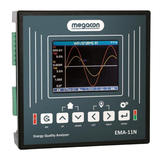
- Page 4 H option Waveforms, Harmonics up to 63 order, DIP/Swell H+ option Waveforms, Harmonics up to 63 order, DIP/Swell, Interrupts (V) Physical Description Alarm and energy pulsing LED Cancellation key Up key Down key Left key Right key Confirmation key and menu Power ON and energy pulsing LED Display ...
- Page 5 pag. 5 / 28...
- Page 6 NOTICE Check the connections Incorrect connection can result in malfunctions and failure of the device. Before starting up the EMA-11N, check that all connections are correct. Device interface The general display of the power meters is shown in the following picture: ...
- Page 7 The user pages are placed in a position that allows the reach them easily starting from the first pages, by pressing the keys. Like all other pages, it is possible to set the EMA-11N to return automatically to the user page after time has elapsed without keystrokes.
- Page 8 The following diagrams show the correlation between kW, kVAR, PF, and inductive or capacitive loads for both the IEC, IEEE and SIGN standards. The EMA-11N permits to select the power factor sign convention. pag. 8 / 28...
- Page 9 Display page navigation Measure Voltage Line-Neutral Power quality Voltage Line-Line Phasor diagram Current DIP / SWELL ** Power factor Interrupts ** Cos phi Expected power Tan phi Active power Incoming data Reactive power Counter Apparent power Logic expression Frequency Custom Active energy IN External data Active energy OUT...
- Page 10 Visualization and measures Navigation STANDARD menu using → keys Analog Voltage Real V1-A1 V2-A2 V3-A3 Crest Min-Max Min-Max Trend Graph time waveform waveform waveform waveform factor L1…3 Harmonics Harmonics V L-N Harmonics V L1 Harmonics V L2 Harmonics V L3 V L-N number format (page 1…4)
- Page 11 Visualization and measures Navigation SMART menu with footer area - specifies the functions assigned to the function keys. KEY 1 KEY 2 KEY 3 KEY 4 KEY 5 KEY 6 Voltage L-N Instantaneous Harmonics 1 * Trend Analog Graph L1 waveform three-phase Harmonics 2 * Min-Max relative...
- Page 12 A supply voltage is required to operate the device. Please consult the technical data or the type plate for the type and level of the possible supply voltage. The EMA-11N can be supplied with an AC / DC multi-range power supply or a AC / DC extra-low voltage power supply: •...
- Page 13 Counters YES / NO Clears counters TB counters YES / NO Clears all counters timebands (excluded total counters). Min-Max YES / NO Reset of MIN and MAX of all readings Max demand YES / NO Reset of Max Demand of all readings Log energies YES / NO Clears all energy meters logs...
- Page 14 MEASURE WINDOW Range Default Upgrade time [min] 1 / 2 / 3 / 5 / 6 / 10 / 12 / 15 / 20 / 30 / 60 The time used to calculate the average, maximum, minimum values and the expected power Type shifting / fixed shifting...
- Page 15 Energies and Counters Setup → Measure → Energies/Counters PRELOAD ENERGY Range Default ΣWh IN [1 = 0.1kWh] 0÷1000000000 ΣWh OUT [1 = 0.1kWh] 0÷1000000000 ΣVArh IN [1 = 0.1kVArh] 0÷1000000000 ΣVArh OUT [1 = 0.1kVArh] 0÷1000000000 ΣVAh [1 = 0.1kAh] 0÷1000000000 Wh IN L1 [1 = 0.1kWh] 0÷1000000000...
- Page 16 Monday Plan Plan 1 ÷ Plan 16 Plan 1 Plan used for this day. ……………… ……………… Sunday Plan Plan 1 ÷ Plan 16 Plan 1 Plan used for this day. Holiday Range Default Month holiday 1 January ÷ December January Day holiday 1 1 ÷...
- Page 17 User pages Setup → User page TYPE Range Default User page 1 instant / averages / energies / setpoint instant User page 2 instant / averages / energies / setpoint instant User page 3 instant / averages / energies / setpoint instant User page 4 instant / averages / energies / setpoint...
- Page 18 MENU AVAILABLE ONLY FOR MASTER MODE SELECTION COM 1 & 2 SLAVE TIPOLOGY Range Default Slave node 1 TTC-V / CTT-4 / … Type of device connected to the address 1 ……………….. Slave node 20 TTC-V / CTT-4 / ... Type of device connected to the address 20 MENU AVAILABLE ONLY FOR MASTER MODE SELECTION COM 1 &...
- Page 19 Setup → I/O DIGITAL OUTPUT (n=1…2) Range Default State 0 / 1 Select 1 for close the DO, 0 to open Level Active low / Active high Active high Normal status of the output. Allows to reverse the logic of the output function Mode Status / Pulse / Setpoint Status...
- Page 20 Alarm setpoint Setup → Setpoint SETPOINT (n=1…32) Range Default Enable Yes / No Enable or disable the setpoint function. Source Internal measures / Measures node X Internal measures Select the instrument from which the measure to analyze it will be read. Group See Acronyms Group table Selection of the group for the actual setpoint if it is set Internal measures as Source.
- Page 21 - in the period and in the timetable: the log is active (on the selected days of the week) in the selected period and time; - trigger: the log is active when the status set is verified; Sampling 1sec/…/60min/end of day/end of week/end of month/end of year 15 min Acquisition timing.
- Page 22 Group 1 --- / instantaneous / average / energies / digital input / counters /analog input / math Selection of the group for the first operand if it is set Internal measures as Source. Item 1 If the selected Group is instantaneous or average or energies, see the acronym in the relative table.
- Page 23 (5) Single-phase measuring, two conductors, without voltage transformers, (6) Three-phase measuring, four conductors, balanced multiple loads, with one current transformer. with three current transformers. Connection type 1PH Connection type 3PH ML BAL (7) Single-phase measuring, two conductors, without voltage transformers, (8) Two-phase measuring, three conductors, unbalanced loads, without with one current transformer.
- Page 24 (9) Single-phase measuring, two conductors, with voltage transformers, with three current transformer. Connection type 3X1PH Wiring table SYSTEM VOLTAGE ● ● ● ● PHASE VOLTAGE L ● ● ● ● ● ● ● ● PHASE VOLTAGE L ● ● ● ●...
- Page 25 THD VOLTAGE L ● ● ● ● ● ● ● ● THD VOLTAGE L ● ● ● ● ● ● ● THD VOLTAGE L ● ● ● ● ● ● THD CURRENT L ● ● ● ● ● ● ● ●...
- Page 26 Appendix 1 Acronyms group table Acronym Instantaneous Average Energies Setpoint Acronyms table of Instantaneous group Acronym Description Acronym Description Acronym Description ΣV System Voltage ΣVA System Apparent Power THD A2 THD Current L2 Voltage L1 Apparent Power L1 THD A3 THD Current L3 Voltage L2 Apparent Power L2...
- Page 27 IEC62053-22 compliant Harmonics up to 63 Harmonics – IEC62053-22 Refresh rate ~ 200 ms Voltage inputs Type of input Three phase + Neutral Measurement range 30 ÷ 400 VAC L-N 52 ÷ 693 VAC L-L Frequency range 50 - 60 Hz Note: V1 terminal must be connected Method of measuring True RMS value...
- Page 28 Relative humidity 5…95% Certifications and compliance Reference standards CEI EN 61000-6-2:2006 CEI EN 61000-6-4:2007 CEI EN 61010-1:2013 For further details please contact: Megacon AB Ranhammarsvägen 20 S-168 67 Bromma, Sweden Phone: +46 (0)8-402 42 50 www.megacon.se pag. 28 / 28...
Need help?
Do you have a question about the EMA-11N and is the answer not in the manual?
Questions and answers