Advertisement
Quick Links
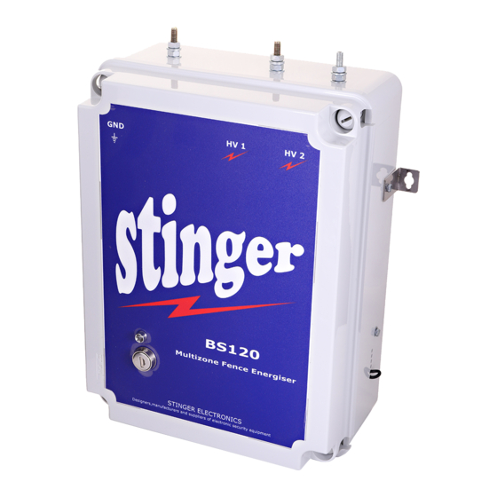
STINGER ELECTRONICS (PTY) LTD BS120 INSTRUCTION MANUAL
THE "STINGER" BS120 SECURITY FENCE ENERGISER.
This user friendly unit has been designed for ease of operation, reliability and Simple operation of the
controls.
A fully computer controlled and integrated perimeter protection system with multiple units is easy to
assemble.
The unit has the following features:
A novel alarm monitoring system (SA Patent No. 99/5728)capable of protecting up to 20 zones. An
alarm condition will occur if the fence live wire is either cut or short circuited during 3 consecutive
pulses in the same zone.
The HV monitor system ensures stable zone information with no drift due to temperature or
corrosion.
Zone programming is very simple.
Fence Voltage can be switched to "Low Voltage" (800V) or "High Voltage"(8500V)
A warning will be given if the fence voltage drops below a level of 3000V due to a system fault.
All controls are located on the remote control unit. Communication between this unit and the
energiser is via a RS485 data link (4 core comms cable), via an RF link or via fibre optic cable.
Multiple Remote Control Units can be connected to one BS120 unit, in which case any control unit can
be programmed to be the "Master" control unit or a "Slave" control unit.
The remote control unit can address up to 13 energizers. If multiple energizers are selected,
synchronization can be automatically
Printed: 4/26/2019
applied.
REF:03/2018
Page 1 of 20
Advertisement

Related Manuals for Stinger BS120

Summary of Contents for Stinger BS120
- Page 1 RS485 data link (4 core comms cable), via an RF link or via fibre optic cable. Multiple Remote Control Units can be connected to one BS120 unit, in which case any control unit can be programmed to be the ”Master” control unit or a ”Slave” control unit. ...
-
Page 2: Specifications
The output voltage of each energizer can be viewed at the LCD Panel and will also be logged via the computer program. The software allows for pulse synchronisation of multiple BS120 units. The zones have to be series wired and must be series connected to each other. - Page 3 Communicates via the computer comm. port and an RS485 to RS232 converter with up to 125 BS120 units via a two wire cable, RF data link or fibre optic cable. Full control of all units is possible via simple configure and setting-up windows.
- Page 4 STINGER ELECTRONICS (PTY) LTD BS120 INSTRUCTION MANUAL REF:03/2018 Earthing practice The above picture indicates how earthing should be done. This picture only shows the earthing required to protect the energizer against lightning. General fence earthing depends on external factors like ground conduction etc.
-
Page 5: Installation Tips
This value relates to any energizer being used. The resistance of ahumanbody has been standardized at 500 Ohms.) 8 Fence monitor lights : Recommended maximum three per BS120 Energizer, as each fence monitor light draws +-0,4J. Page 5 of 20... - Page 6 It is in this case important that the parallel connections are repeated at the end of each zone as shown above. For more information please refer to “Stinger Specification for construction of electric fencing” available on request. Page 6 of 20...
- Page 7 Long fences can be operated with multiple energizers, provided these units are synchronized. Stinger has SABS approval for such a system. Each energizer can feed one live wire. The advantage of this system is that no trenching, cabling or solar panels are required, as all units are located inside the guard house.
- Page 8 1 2 3 4 1 2 3 4 5 6 CONNECTOR BLOCK USE STINGER LIHGTNING DIVERTERS BETWEEN THE ENERGIZER GND CONNECTION AND THE HV1 AND HV2 OUTPUTS. USE A MAINS LIGHTNING PROTECTOR AT THE MAINS INPUT TO THE UNIT. Please note: The instrument is to be installed inside a building or inside a water tight enclosure.
- Page 9 99 events memory. Data can be retrieved via LCD screen. Pin protected user menu and -installer menu. All energizer settings can be addressed via the keypad. The BS120/BS102SMS control unit features an optional built-in modem with full SMSout capability. 1 Fault Messages...
- Page 10 STINGER ELECTRONICS (PTY) LTD BS120 INSTRUCTION MANUAL REF:03/2018 THE FOLLOWING FAULTS CAN BE DISPLAYED: 2007/01/01 0:00:17 UNIT1 H 20 ZONES ! Open Circuit ! (RESET) (MENU) The system is in the HIGH voltage mode and has detected that the live wire has been cut, resulting in an open circuit indication.
- Page 11 STINGER ELECTRONICS (PTY) LTD BS120 INSTRUCTION MANUAL REF:03/2018 Battery low indication. The battery voltage is down to a critically low level, the unit will switch off sometime in the next few hours. 2007/01/01 0:00:17 UNIT1 H 20 Zones ! HT Failure !
- Page 12 (Exit) (Menu) Exit the user menu. New settings will only come into effect after exiting the menu. 3 Advanced Menu BS120(Press both keys simultaneouslyfor3 seconds) - - - --- Advanced Menu- - - - - - 1 Enter Pin Code...
- Page 13 A BS120 energiser was found, continue ? (Retry) (Continue) The system has detected that the display unit has been connected to a BS120 energizer. Press “continue” to proceed. - - - --- Advanced Menu- - - - 3.4 Enter ‘Power mode’...
- Page 14 STINGER ELECTRONICS (PTY) LTD BS120 INSTRUCTION MANUAL REF:03/2018 - - - --- Advanced Menu- - - - 3.7 Select zone to Change, zone5 (Increase) (Accept) First select the zone to be changed by pressing “Increase” - - - --- Advanced Menu- - - - 3.8...
- Page 15 STINGER ELECTRONICS (PTY) LTD BS120 INSTRUCTION MANUAL REF:03/2018 - - - --- Advanced Menu- - - - - 7.0 Sync Energizers Enabled (Disable) (Next Menu) With only one energizer connected, the LCD keypad will send the broadcast address “255”. If the address of this energizer has not been modified, it will reply with the address 0.
- Page 16 STINGER ELECTRONICS (PTY) LTD BS120 INSTRUCTION MANUAL REF:03/2018 If you want to cancel the address change in case of a mistake, press “no” - - - --- Advanced Menu- - - - - 9.6 Address change Cancelled by user (Redo) (No) This menu confirms cancellation of the address change procedure.
- Page 17 STINGER ELECTRONICS (PTY) LTD BS120 INSTRUCTION MANUAL REF:03/2018 Press “Seconds” to reach the correct Second. - - - --- Advanced Menu- - - - 10.7 Set time & date 2000/01/01 0:32:48 (Redo) (Next Menu) Press “redo” if you want to repeat the above operation or press “next menu” to proceed.
- Page 18 Change menu pin to 0000?? (ReEnter) (Save) Press “Save” to accept the new PIN Code. Re-enter to redo. OPTIONAL MENU FOR THE BS120/BS102 LCD keypad with SMS modem installed. - - - --- Advanced Menu- - - - 14.0 SMS Settings (Select) (Next Menu) Press “Select”...
- Page 19 Battery voltage is < 11.2V. (Normally under charge > 13 Volts) Mains.F[x] For BS102 Mains Voltage interrupted (N/A for BS120) OpenCt1[x] For BS120 Open circuit of live HT loop, For BS102 Zone 1 open circuit. ArcZ1[x] For BS102 Zone1 HV arcing to ground. ShortZ1[x] For BS102 Zone 1 Full short to ground.
- Page 20 REF:03/2018 LIMITED WARRANTY BS120 Electric Fence Energizer. Stinger Electronics will repair or replace* your product at our discretion without charge, if it proves to be defective, in material or workmanship under use, during the warranty period of one year from the date of original purchase.
Need help?
Do you have a question about the BS120 and is the answer not in the manual?
Questions and answers
How can I set my time and date for bs 120 manual keypad