Table of Contents

Related Manuals for Crystal Vision FRX-VF

Summary of Contents for Crystal Vision FRX-VF
- Page 1 FRX-VF Dual channel fibre optic receiver Crystal Vision Ltd., Lion Technology Park, Station Road East, Whittlesford, Cambridge, CB22 4WL, England. Tel: +44(0) 1223 497049 Fax: +44(0) 1223 497059 sales@crystalvision.tv www.crystalvision.tv...
-
Page 2: Table Of Contents
Link Configuration Inserting cards Rear modules and signal I/O Rear module connections with VR14 Status monitoring Controlling cards via VisionWeb Menu Structure Control Descriptions Status Troubleshooting Card edge monitoring Basic fault finding guide Specification FRX-VF User Manual R1.0 25 November 2016... - Page 3 Although Crystal Vision optical products contain Class 1 devices that have been designed to be safe under all circumstances, you are advised not to look directly into any vacant optical outlet.
-
Page 4: Introduction
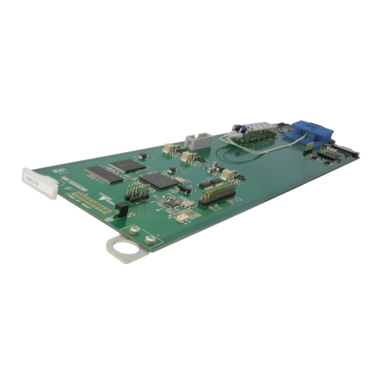
The FRX-VF is a two-channel optical serial digital video receiver and distribution amplifier for 3G, High Definition and Standard Definition video with two reclocked outputs per channel. The FRX-VF is a space-saving 96mm x 325mm module which fits in the standard Vision frames from Crystal Vision. - Page 5 Introduction Remote indications of received power DVB-ASI compatible, all outputs positive polarity Up to 20 FRX-VF cards in a Vision 3 3U frame Less than 100ns delay Remote monitoring and control via VisionPanel, VisionWeb control system, SNMP and the frame active panel FRX-VF User Manual R1.0...
-
Page 6: Hardware Installation
2.1 Board configuration FRX-VF card Link configuration The FRX-VF has no user-selectable links. Any links or controls should remain in their factory set positions. Inserting cards Cards can be plugged in and out of powered Vision frames without damage. Although no electrical damage should occur if a FRX-VF is plugged into the incorrect frame slot, the optical connectors may be damaged. - Page 7 Should the FRX-VF be removed for any length of time it is recommended that the rear module should also be removed and stored with the dust caps fitted.
-
Page 8: Rear Modules And Signal I/O
Rear modules and signal I/O 3 Rear modules and signal I/O The FRX-VF fibre receiver fits into all Vision rack frames from Crystal Vision and can be plugged in and removed while the frame is powered without damage. Vision frames all have a hinged front panel that gives access to the PSUs and all cards. The universal frame wiring system allows any of the interface range of cards to be fitted in any position with the use of removable rear modules. -
Page 9: Status Monitoring
Typical Vision 3 frame homepage The example above shows a FRX-VF card fitted in slot 1 and other Vision cards in slots 2, 3, 5 and 7. Clicking on the FRX-VF card will bring up the card’s Status page, for example: FRX-VF Status page FRX-VF User Manual R1.0... -
Page 10: Menu Structure
VisionWeb monitoring and control pages are accessed by tabs at the bottom of the page which, when selected, offer controls such as LEDs, check boxes, buttons, sliders and labels. The FRX-VF has only a single status page: FRX-VF User Manual R1.0... -
Page 11: Status
10km are possible with single-mode fibre, this distance is dependent on minimal attenuation from junctions etc. Multi-mode fibre installations can expect considerably shorter transmission distances. Single-mode fibre, or any single-mode components should never be used downstream of multi-mode fibre. FRX-VF User Manual R1.0 25 November 2016... -
Page 12: Troubleshooting
FRX-VF front edge 5.2 Basic fault finding guide WARNING: Although Crystal Vision optical products contain Class 1 devices that have been designed to be safe under all circumstances, you are advised not to look directly into any vacant optical outlet. As the visible spectrum is well below the wavelengths used by the FRX- VF there is no point looking into the end of a cable to see if there is a signal. - Page 13 Note: Users of FTX-VF should be aware that the maximum output power of the SFP laser module is 0dBm, and +5dBm for the CWDM module. These levels may necessitate additional attenuation when used in conjunction with the FRX-VF. Poor video signal at receiving end: Check that the received optical power input is ‘GOOD’.
-
Page 14: Specification
VisionWeb Control which is available via the web server on the frame and allows operation using a standard web browser on a computer, tablet or phone. Complimentary SNMP monitoring via frame CPU and Ethernet connection. FRX-VF User Manual R1.0 25 November 2016...
Need help?
Do you have a question about the FRX-VF and is the answer not in the manual?
Questions and answers