WATSON W91 Series Installation, Operation & Maintenance Instructions Manual

WATSON W91 Series Installation, Operation & Maintenance Instructions Manual

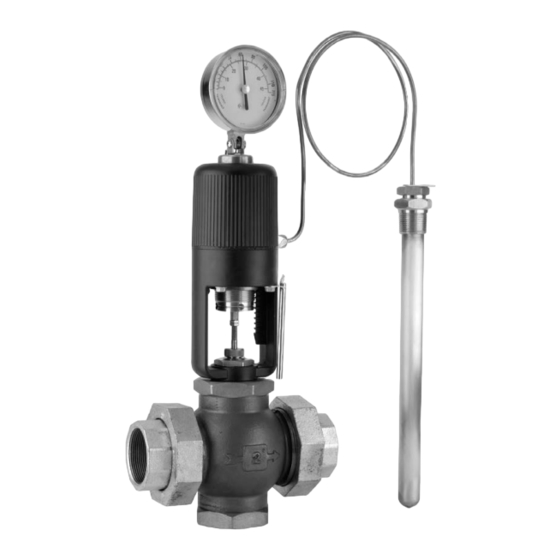
Self-operating temperature regulator

Advertisement

Quick Links

2440300 Rev A
Page 83
Series W91/94 Self-Operating Temperature Regulator
Installation, Operation & Maintenance Instructions

Advertisement

Table of Contents
loading

Summary of Contents for WATSON W91 Series

  • Page 1 2440300 Rev A Page 83 Series W91/94 Self-Operating Temperature Regulator Installation, Operation & Maintenance Instructions...
  • Page 2: Table Of Contents

    Installation, Operation & Maintenance Manual TABLE OF CONTENTS Principles of Operation of the Regulator ..................2 Pressure-Temperature Limits .....................2 Installation ..........................3 Sensing Bulb-Location & Installation...................3 Placing Regulator into Operation & Setting Control Point .............4 Routine Service .........................5 Stem Seal Packing........................5 Checking the Regulator for Proper Action ...................6 Repairing Valve Body Assembly ....................7 Reversing the Valve Action ......................9 3-Way Regulator-Installation &...
  • Page 3: Principles Of Operation Of The Regulator

    PRINCIPLES OF OPERATION OF THE REGULATOR The Series W91/W94 Temperature Regulator operates on the vapor pressure principle. The thermally sensitive bulb of the instrument contains a fluid that creates a vapor which increases or decreases in pressure as the sensing bulb temperature increases or decreases.
  • Page 4: Installation

    INSTALLATION Deciding the Location for the Regulator The regulator should be installed in an accessible location on horizontal piping. Possible damage from moving parts, splashing of corrosive liquids, vibration, heat, fluid pulsations, etc., should be considered in deciding the location. Similar consideration should also be given to the connecting tubing and bulb.
  • Page 5: Placing Regulator Into Operation & Setting Control Point

    When installed in a pipeline, continuous flow past the sensing bulb must be maintained to obtain continuous temperature signal to the regulator. If the flow stops, the pipeline may cool or warm to local room temperature causing false reactions from the regulating valve. On some systems this may require a small by-pass flow line around the valve to maintain representative system temperatures at the sensing bulb.
  • Page 6: Routine Service

    Observe the controlled temperature after it stabilizes and re-adjust the adjusting screw as required to obtain the desired control point. Initial over shooting may occur until the system approaches equilibrium. Allow sufficient time for correction to take place after each adjustment before further changing the setting. Be certain that all manual valves in the main flow line are fully open and not restricting flow.
  • Page 7: Checking The Regulator For Proper Action

    5. Remove the packing nut from the valve bonnet. 6. Remove all old packing, adapters and spring from the valve bonnet. One technique is to admit a small amount of pressure into the valve body until the packing is forced out of the stuffing box. Shield the bonnet as some spray may occur as the packing emerges.
  • Page 8: Repairing Valve Body Assembly

    On all other model of actuators: 1. Record the current adjusting screw setting relative to the reference scale. 2. Set the adjustment screw to approximately “5” on the reference scale. 3. Remove the sensing bulb from the Thermowell or process. 4.
  • Page 9 Figure 3 Figure 4 Figure 5 Replacing Valve Body Assembly 1. Unless already completed, install two locknuts onto valve stem. Dim. A Valve a. Thread locknuts loosely onto the valve stem. Size ACTION IN to Close OUT to CLOSE b. Push or pull the valve stem as appropriate to fully CLOSE a two 2-1/4"...
  • Page 10: Reversing The Valve Action

    REVERSING THE VALVE ACTION ½” – 2” Valve Sizes Only 1. Stem In-To-Close valves close with temperature increase and inward stem motion. 2. Stem Out-To-Close valves close with temperature decrease and outward stem motion. 3. On a regulator these valves are used for COOLING. ½”...
  • Page 11: 3-Way Regulator-Installation & Maintenance

    NOTE: The arrow cast on the valve body always points in the direction of flow for both assemblies. 10. Replace the cross pin. a) If the holes are aligned correctly, when holding the valve plug by the valve stem and shaking it like a rattle, an audible rattle will be both felt and heard.
  • Page 12 FOR MIXING OR DIVERTING MIXING DIVERTING FLOW DIAGRAM FLOW DIAGRAM TEMPERATURE COLD TEMPERATURE COLD CLOSED CLOSED TEMPERATURE SET POINT TEMPERATURE SET POINT LOWER UPPER PORT PORT TEMPERATURE HOT TEMPERATURE HOT CLOSED CLOSED COMMON PORT NOTE: This valve is not to be used for Steam or Temperature over 350F ½”...
  • Page 13: Typical Applications

    TYPICAL APPLICATIONS Typical Heat Exchanger Application Using a Self-Op 2-Way Valve HEATING Use an In-to-CLOSE Valve RETURN COOLING Use an In-to-OPEN Valve PROCESS STEAM WATER INLET Process Side Influence Side STEAM OR WATER RETURN FROM PROCESS HEAT EXCHANGER Typical Heat Exchanger Application Using a Self-Op 3-Way Diverting Valve HEATING Connect Upper Port (C) to Water/Glycol Return...
  • Page 14 TYPICAL APPLICATIONS Typical Heating Application Using a Self-Operating Temperature Regulator Sensor installed directly into Process Vessel using Sensor installed directly Thermowell HOT WATER into tank using STORAGE Thermowell TANK W91 with In-to-Close Valve STEAM INLET STEAM WATER TO TRAP THEN BOILER Typical Fuel Oil Storage Heating Application Using a Self-Operating Regulator Sensor installed...
  • Page 15: Troubleshooting Guide

    TROUBLE SHOOTING GUIDE PROBLEM: ERRATIC CONTROL CAUSES CORRECTIONS 1. Bent or binding valve stem. 1. Replace with free running stem. 2. Packing binding valve stem. 2. Replace packing set. 3. Poor bulb location. 3. Relocate bulb to more representative average temperature location or add agitation.
  • Page 16 TROUBLE SHOOTING GUIDE PROBLEM: TEMPERATURE REMAINS BELOW THE DESIRED CONTROL POINT CAUSES CORRECTIONS 1. Adjusting setting too low. 1. Raise setting. 2. Bulb at hot location. 2. Relocate bulb to more representative average temperature location or add agitation. 3. Stem adjustment too long. 3.

This manual is also suitable for:

W94 series

Table of Contents