Table of Contents
Advertisement
Quick Links
TNC-M14-CNC CONTROLLER
THIS MANUAL CONTAINS INFORMATION FOR INSTALLING AND OPERATING THE
FOLLOWING PRODUCT:
TNC-M14- CNC CONTROLLER
"TINY CONTROLS" AND THE TINY CONTROLS COMPANY'S LOGO ARE COPYRIGHT OF
TINY CONTROLS (P) LTD. COMPANY. OTHER TRADEMARKS, TRADE NAMES, AND SERVICE
MARKS OWNED OR REGISTERED BY ANY OTHER COMPANY AND USED IN THIS MANUAL
ARE THE PROPERTY OF THEIR RESPECTIVE COMPANIES.
TINY CONTROLS PRIVATE LIMITED
C-55, NISHAT PARK, KAKROLA MOR, NEW DELHI, INDIA – 110078
WEB: http://www.tinycontrols.com
PHONE: +91-11-2533-1567, +91-991-119-3210
Document: Operation Manual
Document #: TNC-M14-m
Document Rev: 1.0
Product: CNC controller
Product Rev: 1.0
Created: Oct-2013
1
Advertisement
Table of Contents

Related Manuals for TINY TNC-M14-CNC

Summary of Contents for TINY TNC-M14-CNC
- Page 1 FOLLOWING PRODUCT: TNC-M14- CNC CONTROLLER “TINY CONTROLS” AND THE TINY CONTROLS COMPANY’S LOGO ARE COPYRIGHT OF TINY CONTROLS (P) LTD. COMPANY. OTHER TRADEMARKS, TRADE NAMES, AND SERVICE MARKS OWNED OR REGISTERED BY ANY OTHER COMPANY AND USED IN THIS MANUAL ARE THE PROPERTY OF THEIR RESPECTIVE COMPANIES.
-
Page 2: Table Of Contents
CONTENTS 1. SIGNS USED IN MANUAL 2. CNC CONTROLLER INCLUDES 3. MECHANICAL INSTALLATION 4. INTRODUCTION- TNC-M14- CNC CONTROLLER 5. FEATURES 6. CNC CONTROL BOARD SPECIFICATIONS 7. CNC CONTROLLER BOARD TERMINALS 8. CONNECTING OUTPUTS 9. CONNECTING INPUTS 10. CNC CONTROL BOARD CONNECTION WITH PEN DRIVE 11. - Page 3 33. DATA FILE 34. DEFAULT PROFILES VALUES 35. KEY FUNCTIONS: NAVIGATION KEYS 36. NUMERIC KEYS 37. FEED RATE OVERRIDE AND SPINDLE SPEED OVERRIDE 38. G-CODE ALLOWED TO USE † 39. M CODES ALLOWED TO USE † 40. FORMAT OF A G-CODE LINE 41.
-
Page 4: Signs Used In Manual
SIGNS USED IN MANUAL Warning: A warning contains information, which is essential for avoiding a safety hazard. Caution: A caution contains information, which is necessary for avoiding a risk of damage to the product or other equipment. Note: This icon indicates information which, if not heeded, can result in the CNC controller not operating to full efficiency, as well as information concerning incorrect operations. - Page 5 Don’t turn the main circuit power on or off in order to start or stop CNC controller operation. In general, sheathes and covers of the control signal cables and wires are not specifically designed to withstand a high electric field (i.e. reinforced insulation is not applied). Therefore, if a control signal cable or wire comes into direct contact with a live conductor of the main circuit, the insulation of the sheath or the cover might break down, which would expose the signal wire to a high voltage of the main circuit.
-
Page 6: Cnc Controller Includes
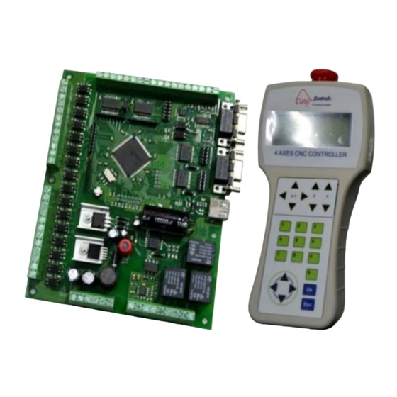
CNC CONTROLLER INCLUDES Control Board Handheld pendant 3mm Serial cable connected to the pendant. MECHANICAL INSTALLATION:... -
Page 7: Introduction- Tnc-M14-Cnc Controller
INTRODUCTION- TNC-M14-CNC CONTROLLER CNC controller is a G-code programmable controller with step and direction outputs for stepper drivers. The three axes X, Y and Z are linear whereas the 4 axis is rotary and can be configured as either A, B or C axis, providing flexibility to system. -
Page 8: Features
FEATURES Totally independent single board solution. 32 digital + 2 analog + 1 isolated analog + 3 relay outputs. 16 isolated inputs. Low jitter 150 KHz Pulse rate on each axis. Constant velocity (with look ahead) and exact stop path modes. Interpolation –... -
Page 9: Cnc Control Board Specifications
CNC CONTROL BOARD SPECIFICATIONS Contents Specifications Processor 32 bit processor Working coordinates 6 working coordinates Display 20x4 alphanumeric LCD USB Host Port USB-2.0 Port Communication Terminal 1 Serial Terminal for pendant Communication Terminal 2 Serial Terminal (PLC interface) 8.3 format (8 lettered name+3 lettered extension File Format name) Axes... -
Page 10: Cnc Controller Board Terminals
CNC CONTROLLER BOARD TERMINALS Misc Outputs 1-6 24 V TOOL ZERO IN Connection to Pendant BLOCK MODE IN MISC INPUT 1 MISC INPUT 2 Misc Outputs 7-14 24 V X HOME IN Y HOME IN Z HOME IN 4 HOME IN Misc Outputs 15-22 Pen drive slot 24 V... -
Page 11: Connecting Outputs
CONNECTING OUTPUTS Digital Outputs: The digital outputs are as following: UTPUTS FOR PINDLE DRIVE Step output: 1 Direction output: 1 CNC controller board has a buffered step and SPINDLE STEP OUT direction output for spindle drive. The step frequency SPINDLE DIR OUT is user programmable and ranges up to 20 KHz. - Page 12 If 5V input is fed from VFD to 10V Analog IN, an analog 10 V ANALOG IN output in range of 0-5V can be drawn from terminal 0-10V 0-10V ANALG OUT 0V IN Analog OUT terminal. & C PINDLE NABLE OOLANT UTPUTS SPINDLE...
-
Page 13: Connecting Inputs
M54.15 M54.16 Figure shows the connector 3 outputs with respective M54.17 M54.18 Mcode. These are open collector outputs and can be M54.19 M54.20 made ON/OFF in G-code. These outputs generate Active M54.21 M54.22 high output when made ON in Gcode. M54.01-M54.22: To make the Misc output ON. - Page 14 b. T ERO INPUT An input signal is received on tool zero input pin when the tool touches the sensor plate. Tool Zero IN terminal recieves this signal by a wire whose other end is connected to the tool by a clamp. LOCK MODE INPUT 24 V An external input is given to the block mode input pin of the...
-
Page 15: Cnc Control Board Connection With Pen Drive
in board. These input terminals are Misc input terminal 3, 4, 5 and 6. And the function assigned to them are Hold/ resume, stop, start and emergency resectively. These functions are discussed further in manual. CNC CONTROL BOARD CONNECTION WITH PEN DRIVE Connect the USB flash drive to the USB slot on the control board as shown below: The first LCD screen is displayed when the pen drive is detected by the controller. -
Page 16: Connection Diagram
SPINDLE DIR CONNECTION DIAGRAM SPINDLE STEP Connection to pendant SPINDLE ON/OFF ANALOG OUT ANALOG IN Coolant Flood Coolant Mist 4+ Limit switch 4- Limit switch Z+ Limit switch Z- Limit switch Y+ Limit switch Y- Limit switch X+ Limit switch X- Limit switch 4-Home switch Z-Home switch... -
Page 17: Axes And Spindle Outputs Connections With Drives
AXES AND SPINDLE OUTPUTS CONNECTIONS WITH DRIVES X DIR OUT X STEP OUT Y DIR OUT Y STEP OUT Z DIR OUT Z STEP OUT DIR OUT STEP OUT SPINDLE DIR OUT SPINDLE STEP OUT Step... -
Page 18: Block Mode And Tool Zero Connections
BLOCK MODE AND TOOL ZERO CONNECTIONS Spindle motor Collet Clip holding wire Tool 24 V TOOL ZERO IN Work bed Sensor Plate BLOCK MODE IN Shield wire MISC INPUT 1 MISC INPUT 2 CNC control board should be installed in dust free environment with suitable temperature and humidity conditions. -
Page 19: Home Inputs Connections With Home Switches
HOME INPUTS CONNECTIONS WITH HOME SWITCHES X-HOME SWITCH X HOME IN Y HOME IN Z HOME IN 4 HOME IN Y-HOME SWITCH Shield wire Z-HOME SWITCH -HOME SWITCH COOLANT, SPINDLE DRIVE AND VFD CONNECTIONS 10V ANOLOG IN Analog input to microcontroller 0-10V ANOLOG OUT Analog input from microcontroller 0V-IN... -
Page 20: Limit Inputs Connections With Limit Switches
LIMIT SWITCHES CONNECTIONS WITH CONTROLLER BOARD X+ LIIMIT SWITCH X LIMIT IN Y LIMIT IN Z LIMIT IN LIMIT IN X- LIIMIT SWITCH Shield wire Y+ LIIMIT SWITCH Y- LIIMIT SWITCH Z+ LIIMIT SWITCH Z- LIIMIT SWITCH + LIIMIT SWITCH - LIMIT SWITCH... -
Page 21: Mounting Instructions
MISC INPUTS CONNECTIONS WITH CONTROLLER BOARD Hold/ resume Stop Misc Input 3 Misc Input 4 Misc Input 5 Misc Input 6 Start Emergency MOUNTING INSTRUCTIONS CNC Controller board can be mounted in a box or can be used open. A proper arrangement of emergency button must be made in CNC controller board installation. -
Page 22: Inputs And Outputs Specifications For Control Board
INPUTS AND OUTPUTS SPECIFICATIONS FOR CONTROL BOARD CONTROL OUTPUTS: & C PINDLE OOLANT OUTPUTS Terminal Name Type Pin function X-axis pulse output terminal X-axis Step pulse output voltage = 5V Buffered output current = 20mA X-axis Signal output terminal X-axis Dir signal output voltage = 5V Buffered output current = 20mA... - Page 23 NALOG OUTPUTS Terminal Name Type Pin function Output voltage =0–10V (When input is Analog output terminal Isolated 10V) current = 20mA Output voltage = 0–10 V Analog output terminal (0-10 V) Non-Isolated current = 20mA Output voltage = 0–10 V Analog output terminal (0-10 V) Non-Isolated current = 20mA...
- Page 24 Terminal Name Type Pin function Tool zero Optoisolated input Set the tool to zero position Block mode One line of Gcode file is executed Optoisolated input when an input is given at this pin X-Home IN Optoisolated input Accept Homing input signal for X- axis Y-Home IN Optoisolated input...
-
Page 25: Hand Held Pendant
HAND HELD PENDANT The Pendant can be taken as hand held control for a machine tool. This device is used in conjunction with CNC controller board to give user a complete access to the schematic and work area. The pendant and control board makes... - Page 26 Pressing Esc repeatedly makes control to return to the main menu. Pressing Esc in idle mode shows the product part number and the version of the CNC controller. 3. NAVIGATION KEYS PANEL (UP, DOWN, RIGHT, LEFT): In editing, the navigation keys are used to navigate the cursor. These also serve the alternate function in some modes.
- Page 27 5. LCD DISPLAY (20 An LCD is incorporated into the design for the pendant to give the user an ability to access the information of parameters. It indicates all the information related to MENUS or MODES. ‘*’ shows the current selected menu function. To enter in a menu function, move to the function by using up-down navigation key and press Ok.
-
Page 28: Emergency Button
EMERGENCY BUTTON User can give an emergency input by a red color button at the top of pendant. When this button is pressed, the motion stops however it does not cut down the power supply to CNC controller. On pressing the button, the machine instantly stops since all the “control outputs”... -
Page 29: Keys Functions In Various Modes
KEYS FUNCTIONS IN VARIOUS MODES Most of the keys have different functions in different modes. Following table shows the functioning of keys in various modes. Following are the functions of numeric and the jog keys. IDLE MODE HOLD MODE RUN MODE Jog X- Jog X- Jog X+... - Page 30 IDLE MODE HOLD MODE RUN MODE Display WC/MC* Display WC/MC* Display WC/MC* LEFT LEFT Manual override mode Manual override mode (Long Press) Jog step/Jog Cont./Jog Jog step/Jog Cont./Jog Jog step/Jog Cont./Jog RIGHT fast fast fast RIGHT Jog Offline Jog Offline (Long Press) Jog Factor+/ Step-size Jog Factor+/ Step-size...
-
Page 31: Cnc Controller Board Connections With Pendant
CNC CONTROLLER BOARD CONNECTIONS WITH PENDANT The controller makes communication with pendant through RS-232 serial port. There are two serial communication channels on the CNC controller board. One dedicated Serial communication channel is made between the hand held pendant and the CNC control board while the other channel can be made between the Controller board and any peripheral. -
Page 32: Description Of Displays In Various States Of Machine
DESCRIPTION OF DISPLAYS IN VARIOUS STATES OF MACHINE ACHINE Spindle On Coordinates for machine position Line no. Spindle speed Jog mode Current Working Coordinate system Jog factor Machine Run Tool no The illustration for the above screen is shown below: Current working Coordinate system: Here “1”... - Page 33 Spindle Off ACHINE Coordinates for machine position Line no. Spindle speed Jog mode Current Jog factor Working Machine Jog Coordinate system Tool no The current working coordinate system, Coordinates for machine position, Tool number, Line number, Jog mode, Jog factor, Spindle Speed, Spindle On/Off have their usual meaning.
- Page 34 ACHINE Line no. Current Working Spindle speed Coordinate Jog mode system Jog factor Machine Stop Tool no Current working Coordinate system: Here “0” shows that machine produces the coordinated motion to the programmed point in “Absolute coordinate system”. The Coordinates for machine position, Tool number, Line number, Jog mode, Jog factor, Spindle Speed, Spindle On/Off have their usual meaning.
-
Page 35: Operating The Cnc Controller
OPERATING THE CNC CONTROLLER MAIN MENU: When the power is applied to the control board, the “ON” status is displayed by the glowing of red LED on the control board and a splash screen appears on LCD showing version and the product part number. If the pen drive is not mounted, a message appears as shown by the screen adjacent. -
Page 36: Structure Tree For Menu Functions
STRUCTURE TREE FOR MENU FUNCTIONS EXACT STOP (G61) X-AXIS ENABLE/DISABLE STEP PULSE DRIVE GENERAL SETTING Y-AXIS STEP PIN CONTINUOUS (G64) PATH MODE STEP PIN BLOCK MODE (G70) MAX RPM Z-AXIS A-AXIS DEFAULT MAX DEVIATION DIR PIN -AXIS B-AXIS MIN RPM ACTIVE PROFILE PROFILE 1 HELP... -
Page 37: General Settings
GENERAL SETTINGS The GENERAL SETTINGS function adjusts Step pulse width, Path mode & Max deviate. Keypad function shows the function of all the keys on pendant in various modes. Diagnosis function allows the operator to diagnose inputs and outputs of the CNC controller. - Page 38 Maximum Deviate function forms the curve at the junction according EVIATE to the deviation factor set. Range for max deviate factor is 1-999. If it is set 1, a curve is formed with the deviation of 0.01mm from the junction point. Higher the value of max deviate, greater is the distance of curve from the junction point.
- Page 39 (G64): ONTINUOUS Enter in path mode and select Continuous. Adjacent screen appears. Confirm or cancel it and exit to previous menu. (G70): LOCK Enter in path mode and select Block mode. Confirm or cancel it and exit to previous menu. Method to access Max Deviate menu: Enter in Max deviate.
- Page 40 Method to access Diagnosis menu: INPUT ANALYSIS: When any input is received by the CNC controller, it shows the corresponding input name on the LCD screen. Following table shows the method to diagnose the outputs: Output Key to be Action to be performed by CNC pressed X-axis outputs Key X+...
-
Page 41: Active Profile
All the outputs of control board can be made OFF by pressing key 0. Outputs can’t be made OFF individually. Press Esc to exit. A message for “Diagnosis complete: System Reboot” appears. ACTIVE PROFILE ACTIVE PROFILE menu make the operator to select a profile and store the General settings, Axis settings, IO settings for spindle, homing and Tool settings for the operation to be controlled by CNC Controller. - Page 42 describes the motion around X-axis, B-axis describes the motion around Y-axis and C- axis describes the motion around Z-axis. For AXIS SETTINGS, make changes in the parameters discussed in this section and save them in desired profile. , Y-A , Z-A &...
- Page 43 MM/MIN: It shows the maximum velocity of the axis. Different axes can have different velocities. The maximum achievable velocity for all axes is: Velocity (max) = (1, 50, 000*60) ⁄ (Steps ⁄mm) Steps/mm remains fixed for axis. The pulse rate varies in accordance with velocity (MM/MIN) for particular axis.
-
Page 44: Io Setting
Select (MM/sec) ^2 and edit the value. Confirm or cancel the modifications made in settings and exit to previous menu. Modify the axes settings for rest 3 axes. APPING Select and enter in 4 AXIS MAPPING. Any one axis can be selected here which user wants to be the rotational axis. - Page 45 Spindle rotates if the spindle drive receives enable signal and spindle is made ON in Gcode file. If spindle is disabled in IO setting and spindle is made ON in G-code file, then spindle does not work. “Spindle enable/disable” is the relay output from CNC Control Board and the relay remains off is spindle is disabled.
-
Page 46: Homing Setting
Select STEP FREQ and modify the values. Confirm or cancel the settings made and Exit to previous menu. HOMING SETTING HOMING SETTING provides settings for an advanced homing cycle with speed configurable options to return to home position. Homing ensures the safety of the machine. -
Page 47: Home Switch Setting
Z-axis uplifts to a height set in this function and then homing of other axes takes place. By this, the tool installed at Z-axis remains safe. The maximum height can be the height of the Z-axis of the machine. This is the delay settled for debouncing of the Home Switch, when EBOUNCE pressed. -
Page 48: Limit Setting
For all axes, it is required to make some settings for home switches. These are: sets the home switch enabled for the axis. It makes the homing of the axis NABLE when key 7 is pressed long. Active high sets the home switch to generate an active low pulse to axis Home-In terminal on the board when the switch got triggered. -
Page 49: Misc Outputs
limit/home is not checked and user need to jog the machine reverse. Press left navigation key long again to exit from manual override mode. Disable the Limit switches for the axes which don’t have the home switches. For all the three axes, it is required to make the following settings for Limit switches. -
Page 50: Tool Settings
any output on the output pin even made ON in Gcode file. Misc output can be set in any of the following state: /HI: If output is set enable high, the output pin generates an active high pulse if output is made ON in Gcode. - Page 51 zero input pin and it stops any further movement instantly to avoid any damage to the tool. At the same time, controller moves the tool upward to a set Back off Distance. At the moment, tool touches sensor metal plate, controller sets Z=0 at the top of work piece and updates current working co-ordinate system as well as DRO (digital readout);...
- Page 52 for tool zero position. Now replace the Tool No. 0 with Tool No. 1 which is 2mm longer than Tool No. 0. Now offset value is 2mm. Tool No. 1 moves 2 mm less distance than Tool No. 0. This offset value can be calculated automatically by AUTO MEASURE OFFSET or manually by MANUAL EDIT OFFSET.
-
Page 53: Data File
DATA FILE Data file function allows loading the General settings, Axes settings, IO settings and Tool settings chose by the user to all the profiles including the active profile. These settings are to be saved in a file named as Settings.tcs which the user creates in the USB Flash drive and can be loaded to all the profiles by “load from file”... -
Page 54: Default Profiles Values
DEFAULT PROFILES VALUES Pull off: 1 mm GENERAL SETTINGS Safe Z Height: 10mm Step pulse width: 4us Debounce delay: 100mS Path mode: Continuous mode OME SWITCH SETTINGS Max Deviation: 5 Home switch Enable (all axes): Active ... -
Page 55: Key Functions: Navigation Keys
KEY FUNCTIONS: NAVIGATION KEYS Functions of keys in Various Modes are shown in table 1.1 and 1.2. This section describes the function of navigation and numeric keys in detail. KEY LEFT: WCS T OGGLE CREEN By default, DRO shows all the coordinates with respect to G54 working coordinate system, which can be identified by the number shown at the left most column of it. - Page 56 KEY RIGHT: J Jogging is used to travel the CNC machine carriage such as CNC machine axis movement. Jogging allows for manual operation of tool by using Jog keys. (The functions of jog keys have been discussed under jog keys panel of Hand held pendant section).
- Page 57 Put machine in idle or hold mode. Press Jog keys of required axis to jog machine. KEY RIGHT L RESS FFLINE In jog offline mode, absolute coordinates got changed and whole WCS shifts to a new position. Due to jogging, position of the machine changes and the coordinates for current position of machine got changed w.r.t.
-
Page 58: Numeric Keys
NUMERIC KEYS OORDINATE These keys are used to update the current working coordinate system (WCS) (G54- G59) and sets machine at zero position for the selected axis in current WCS. Zeroing all the axes sets new origin of current working coordinate system in Idle and Hold mode. -
Page 59: Feed Rate Override And Spindle Speed Override
coordinates are not changed, machine resumes from same position on pressing key 8 for resumption. However if coordinates have been changed, a different procedure for resumption is to be employed. The complete process for resumption is discussed further in this manual. Spindle turns off if Esc button is pressed. KEY 5 L RESS CODE... - Page 60 KEY 6: OVERRIDE SCREEN When the machine is in either of 3 modes, pressing key 6 shows the override screen on the LCD. User can change the percentage of feed rate override using Z jog keys and percentage of spindle speed override using the 4 jog keys.
- Page 61 KEY 7 L : HOMING RESS Homing is the process of finding home switches and bringing machine at a known location. Although this controller is capable of restoring location of machine even after power shut down and shows machine’s current location all the time, there can be some situations during machine operations when its location can’t be identified accurately.
- Page 62 In hold mode, this key can be used to resume execution of G-code file, if all conditions for resumption satisfy. Condition for resumption: USB drive must be mounted. File with same name must exist in USB drive. Contents of Gcode file should not be changed. Operations during resumption in Hold Mode: For hold mode, machine starts moving from current point as normal execution, if there is no change in position, when resumed.
-
Page 63: G-Code Allowed To Use
KEY 0: TOOL 0 Pressing this key starts tool zero process when machine is in idle mode. As the screen shows, this process can be terminated at any time by pressing ‘Esc’ key. Pressing key 0 sets selected tool to tool zero. User can press Esc to cancel tool zero process and stop the tool at that position. -
Page 64: M Codes Allowed To Use
G61: Exact Stop mode G64: Continuous mode G70: Enable Block mode G71: Disable Block mode G80: Cancel Motion Mode G90: Absolute Distance Mode G91: Incremental Distance Mode G92: Offset Coordinate Systems and Set Parameters G92.1: Cancel Offset Coordinate Systems and Set Parameters to Zero G92.2: Cancel Offset Coordinate Systems but do not Reset Parameters G92.3:... -
Page 65: Format Of A G-Code Line
Format of a G-code Line Lines of G-code can be collected in a file to make a program or run a block at a time. Each line can include commands to a machining center to do several different things. G1X5.991Y21.259Z-0.500 For CNC controller, a typical line of code consists of one or more "words". - Page 66 Messages should be displayed on the message display device. Comments not containing messages need not be displayed there. Comment can be written in any of quotation either in single quotes or in double quotes. For example: M75 'tiny controls' M75 "tiny controls"...
-
Page 67: Trouble Shooting
TROUBLE SHOOTING 1. What happens if there is a power cut in between the operation of CNC machine? Ans: Controller can resume the operation on any power interruption saving the current line of G-code and ‘homing’ the machine on power up from last location. 2. - Page 68 Pen Drive not found: Insert the Pen drive and try again. File doesn’t exist: Selected file doesn’t appear on pen drive. Check whether pen drive contains the file or not. Wrong format of file: CNC controller supports the 8.3 formats (8 lettered filename +3 lettered extensions).
-
Page 69: Glossary
GLOSSARY Axis motor: A motor that causes motion in a particular axis. Absolute coordinate system: In an absolute coordinate system, all the references are made to the origin of coordinate system. All the commands of motion are defined by the absolute coordinate referred to origin. Block mode: In the block mode, the machine motion stops at the execution of one programmed line and execute the next line on the trigger of an external input called... - Page 70 Linear interpolation: A translation of linear axis positions into straight vertical, horizontal, or diagonal tool movements. Linear interpolation requires an endpoint and a feed rate. Machine zero point: A fixed zero reference point set by the machine manufacturer. The machine zero is used to define the coordinate based grid system of the CNC machine.
-
Page 71: Index
INDEX Connection Diagrams: Key Down: Jog factor decrement, 57 Numeric keys: CNC control board connection diagram with pen drive, 15 Key 0: Tool 0, 62 Overall connection diagram, 16 Key 1-4: Coordinate zero keys, 57-58 Axes and spindle drive connections, 17 Key 5: Gcode file select, 59 Block mode &...
Need help?
Do you have a question about the TNC-M14-CNC and is the answer not in the manual?
Questions and answers