
Summary of Contents for Parabeam 700-FSK
- Page 1 Parabeam ® LONG RANGE ALERT SYSTEMS INSTALLATION MANUAL SITE CODE: Paratronics Developments Ltd, Kapiti New Zealand Phone/Fax: +64 4 297 2386 | Email: sales@parabeam.co.nz | www.parabeam.co.nz...
- Page 2 Security monitoring of beach properties and sites vulnerable to public access NOTE: The default factory setting is ‘Maximum 10m’ (no jumpers) as 99% of Parabeam® systems sold are • After-hours monitoring of sales yards, nurseries and installed to monitor driveways.
-
Page 3: Installation
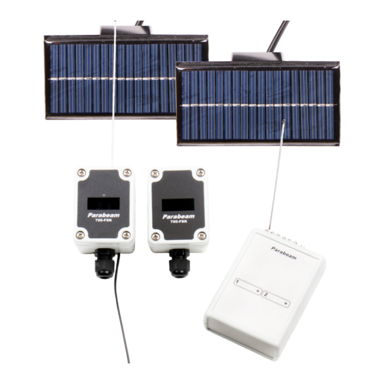
If you wish to test a Parabeam® system indoors, use a large room and ensure the two Beam Units are placed MOUNTING THE BEAM-SET at least 3 metres apart. - Page 4 IMPORTANT: THE FRONT COVERS ON THE TWO BEAM UNITS ARE NOT INTERCHANGEABLE. The Beam Communicator front cover has a small round DIAGRAM 5 window above the main rectangular window. Preparing Solar Panel Wire Page 4 Parabeam® 700-FSK Installation Manual Copyright 2011 Paratronics Developments Ltd, Kapiti, New Zealand...
- Page 5 If needed, adjust the brackets on both beam units Installing the Supplied Antenna to achieve this result. Page 5 Parabeam® 700-FSK Installation Manual Copyright 2011 Paratronics Developments Ltd, Kapiti, New Zealand...
- Page 6 Every Base Receiver comes programmed with a unique four character Site Code, (eg: 9C5A). This code is printed on the label, found on the underside of the Base Receiver. Page 6 Parabeam® 700-FSK Installation Manual Copyright 2011 Paratronics Developments Ltd, Kapiti, New Zealand...
- Page 7 This Site Code is a unique code to every Parabeam® Connect the battery. Wait 30 seconds. 700-FSK Driveway Alert System. The Site Code enables Press the tact switch, keeping pressed for three seconds, several neighbouring Parabeam® systems to operate until the amber LED is permanently lit. The beam without interferring.
- Page 8 • Do not cover the Beam Communicator with timber, fabric or wire mesh as this can reduce connectivity with the Base Receiver. • Parabeam® has not been designed to be installed DIAGRAM 13 indoors. If you wish to test a Parabeam® system...
-
Page 9: Specifications
Options’ to have the Base Receiver interface correctly. shallow water. Below is a table showing the correct alarm panel selection options, depending on how the Zone Common is configured. Page 9 Parabeam® 700-FSK Installation Manual Copyright 2011 Paratronics Developments Ltd, Kapiti, New Zealand... - Page 10 ALARM ON OPEN OR ALARM ON SHORT NEW ZEALAND DIAGRAM 17 shows the base receiver being powered by Free phone 0508 PARABEAM (0508 727 223) the alarm panel and both zones connected to separate zone inputs. AUSTRALIA Free phone 1800 456 736...
-
Page 11: Year Warranty
NOTE: WE WILL NOT ACCEPT FAULTY GOODS WITHOUT AN RMA NUMBER. If your Parabeam® system was installed by a third party installer (eg: an alarm company), please contact them first. If they are not helpful, or no longer exist, please contact Paratronics Developments Ltd, and we will assist you.
Need help?
Do you have a question about the 700-FSK and is the answer not in the manual?
Questions and answers