
Summary of Contents for uhu NORTHSTAR
- Page 1 NORTHSTAR GPS Health Monitor User’s Guide 1201 Executive Drive West Richardson, TX 75081 972.905.0437 info@uhutechnologies.com March 2022...
-
Page 2: Table Of Contents
Table of Contents Getting to know the Northstar .......... 1 Welcome ................1 Package Contents ..............2 Physical Descriptions ............2 Northstar Specifications ............5 GPS Antenna Specifications ..........5 Positioning the GPS Antenna ..........6 Getting Started ..............7 Wiring Diagram .............. - Page 3 3.13 Debug Info ................39 3.14 Display Options ..............39 3.15 Reboot System ..............39 3.16 Update Firmware ..............39 Ordering Information ............. 40 Northstar GPS Health Monitor ..........40 Accessories ................ 40 Appendices ..............41 External JSON Definitions ..........41 5.1.1 Other considerations ..............
-
Page 4: Getting To Know The Northstar
M A R C H 2 0 2 2 1 Getting to know the Northstar 1.1 Welcome The Northstar GPS Health Monitor adds unparalleled situational awareness and threat detection capabilities to any facility that depends on GPS for position or time. Authentic Satellites Spoofing... -
Page 5: Package Contents
M A R C H 2 0 2 2 1.2 Package Contents • Northstar (1U rackmount unit) • 4-element GPS Antenna • Network Cable (RJ-45) • AC Power Cable (IEC 60320 C13) • User’s Guide (this document) • Antenna mounting kit (optionally included) •... - Page 6 This port accepts a 10 MHz reference at up to +6 dBm for timing applications. Auxiliary port This is a multi-use port that can be configured for any one of the following functions: remote RF disconnect, NMEA output messages from the Northstar’s internal GPS receiver, or unmodulated IRIG-B over RS232 (future software update).
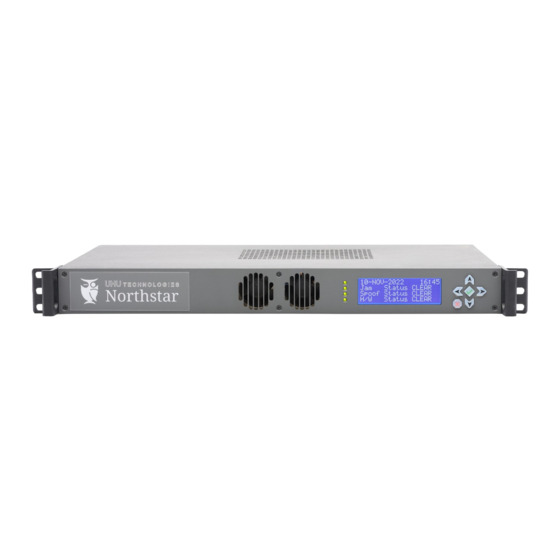
- Page 7 2 0 2 2 The Northstar’s front panel is shown below: Heartbeat LED The Heartbeat LED blinks green when the Northstar is functioning normally. Spoofer LED The Spoofer LED illuminates red when a spoofer alarm is active, green when in clear state, and off when in an unknown state.
-
Page 8: Northstar Specifications
M A R C H 2 0 2 2 1.4 Northstar Specifications Temperature Operating: -40°C to +65°C * Storage: -40°C to +85°C Humidity 5% to 95% RH non-condensing Altitude 5000 m (16,404 ft) Shock 15g/0.53oz, 11ms half sine wave Vibration 10-55 Hz/0.07g, 55-500 Hz/1.0g... -
Page 9: Positioning The Gps Antenna
• Antenna is intended for installation in a restricted access location. • RF coax guidelines: o The Northstar is designed to work with LMR-240-FR coax cable; please check with UHU before using other types of coax. All coax should be of the same type. -
Page 10: Getting Started
RF Disconnect (optional) 2.2 Power ON/OFF Procedures Power the Northstar on by simply flipping the power switch identified in section 1.3 to the “I” position. Before powering the Northstar off using the power switch, it is recommended to follow the following shutdown procedure. -
Page 11: Obtaining An Ip Address
2.3 Obtaining an IP Address Before you can connect to the Web GUI, you must first obtain the IP address of the Northstar. Proceed to section 2.3.1 if your network is DHCP equipped; proceed to section 2.3.2 if your network requires manual IP configuration. -
Page 12: Connect To The Web Gui
Using a web browser (Google Chrome shown below), type the IP address you determined in Section 0 into the address location and press enter. For example, if the IP is 172.16.100.234: The Northstar encrypts all communication using a self-signed SSL certificate. Most Web browsers will complain that the certificate is invalid with a message similar to: For the Chrome browser, first click ADVANCED, and then click PROCEED. -
Page 13: First Time Login
M A R C H 2 0 2 2 2.5 First Time Login Default username: admin Default password: password Type in the default username and password and click “LOG IN.”... -
Page 14: First Time Setup
M A R C H 2 0 2 2 2.6 First Time Setup The first-time setup process walks you through configuring your Northstar. The following configuration will be covered during first-time setup: 2.6.1 Setting the Password This page allows you to change the default password for the “admin” account. The password must be 8 to 20 characters long, have at least one number, and have at least one capitalized letter. -
Page 15: Email Setup
Click the “Restart Cal” button to clear the calibration and restart the process. If a non-standard antenna is being utilized or if the Northstar is being tested by a wavefront simulator, select the appropriate antenna calibration using the drop-down menu and click “Save.”... -
Page 16: Self-Calibration
M A R C H 2 0 2 2 2.7 Self-Calibration The Northstar automatically starts self-calibration after it is powered on for this first time. Self-Calibration is performed in four steps: • Basic calibration • Retrieve initial almanac • Attitude calibration •... - Page 17 M A R C H 2 0 2 2 By clicking on the calibration icon, you will be taken to the calibration status page. This page is can also be found through Settings → Calibration Status. See section 3.12.
-
Page 18: Dashboard
Zero degrees elevation (the horizon) is the outermost circle. Ninety degrees elevation (straight up) is the center of the plot. The blue icons represent the actual GPS satellite position in the sky. The green icons represent the measured (using UHU’s proprietary interferometric algorithms) GPS satellite positions in the sky. - Page 19 M A R C H 2 0 2 2 When the Northstar is in an alarm state, the sky view is updated accordingly: If a jammer and/or spoofer is detected in the environment, each threat will be displayed on the sky view plot and will reflect the threat’s direction with respect to the Northstar’s antenna.
-
Page 20: Map View
Map View is only supported if you have an active connection to the Internet (Map View is disabled by default). Map View displays the Northstar’s current position on a map and displays lines of bearing to any active spoofers or jammers. -
Page 21: Chart View
M A R C H 2 0 2 2 2.8.3 Chart View Chart View takes any data provided by the Northstar and formats it into a chart. -
Page 22: Spectral View
M A R C H 2 0 2 2 2.8.4 Spectral View Spectral View displays the FFT (Fast Fourier Transform) of the antenna inputs. This view is useful for analyzing the spectral shape of jammers. -
Page 23: Time Machine
M A R C H 2 0 2 2 2.8.5 Time Machine The Time Machine allows past events to be displayed in the Sky, Map, or Chart views as if they were occurring in real-time. Once enabled, any arbitrary time since calibration can be selected for viewing. The Time Machine works like a traditional media player, with the ability to play, pause, rewind, and fast forward. - Page 24 M A R C H 2 0 2 2 Viewing a specific event with the Time Machine:...
- Page 25 M A R C H 2 0 2 2 Once a specific event has been selected, the display will update as shown below: The mouse cursor can be clicked (or dragged) anywhere along the timeline to change the time. Additionally, the media controls are listed below: Play Pause...
-
Page 26: Power Bar
Bar includes out-of-band power/interference and the Spectral View does not. The Power Bar can be very useful during initial setup and installation, as it can provide clues to local interference (large electric motors, generators, industrial equipment, etc.) that might prevent the Northstar from calibrating. -
Page 27: Recorder
M A R C H 2 0 2 2 2.9 Recorder The optionally equipped I/Q recorder stores narrowband (2.6 Msps) I/Q data on an internal solid-state disk (SSD). The SSD is configured as a large circular buffer. Antenna channel A is continuously recorded. The recorder settings are described in Section 3.6. -
Page 28: Recording Interface - Manual
M A R C H 2 0 2 2 2.9.2 Recording Interface - Manual The recorder can be accessed through the GUI in multiple ways. The first is by manually viewing the list of recordings and protected recordings. Go to Settings → Recorder Setup → View Recordings In this view, recording segments can be downloaded, protected, and unprotected:... - Page 29 M A R C H 2 0 2 2 Once a segment is selected, the start time and segment length fields can be manually adjusted, as often a single segment is too large to download. Clicking the Start Time field opens a calendar view:...
- Page 30 M A R C H 2 0 2 2 Similarly, the length field can be adjusted by either entering the length in seconds, or by using the up/down arrow keys:...
-
Page 31: Recording Interface - Events
M A R C H 2 0 2 2 2.9.3 Recording Interface - Events The second method of accessing the recorder is through the events list. If a recording segment exists that encompasses the start and end time of a given event, the GUI will display a “Manage I/Q”... - Page 32 M A R C H 2 0 2 2 This action will cause details of both the event and the recording segment to be displayed: Within a protected recording segment, please note that the start time and segment length can be manually changed (to select a shorter segment to download, for example);...
-
Page 33: Recording Interface - Time Machine
M A R C H 2 0 2 2 2.9.4 Recording Interface - Time Machine The final method of accessing recordings is through the time machine. As shown below, recordings are available, but currently not being displayed on the time machine. Click “Recordings off” to toggle the setting and display the available recordings:... - Page 34 M A R C H 2 0 2 2 Now, unprotected segments will be shown in orange and protected segments will be shown in green:...
- Page 35 M A R C H 2 0 2 2 Clicking on a particular segment will take you to the recording list and highlight to selected recording:...
-
Page 36: I/Q File Format
M A R C H 2 0 2 2 2.9.5 I/Q File Format Please note that all fields are in little-endian format. Also note that the file header data is not aligned to data-type boundaries, so the user must use caution when accessing these fields. Byte Type Width... -
Page 37: Settings
Chapter M A R C H 2 0 2 2 3 Settings The settings menu can be accessed from any page:... -
Page 38: Alerts Setup
Click the “Restart Cal” button to clear the calibration and restart the process. If a non-standard antenna is being utilized or if the Northstar is being tested by a wavefront simulator, select the appropriate antenna calibration using the drop-down menu and click “Save.”... -
Page 39: Snmp Setup
M A R C H 2 0 2 2 3.8 SNMP Setup This page allows you to configure Simple Network Management Protocol (SNMP). If enabled, the port number can be customized. Additionally, v1/v2c and/or v3 SNMP can be enabled or disabled, depending on network requirements. - Page 40 M A R C H 2 0 2 2 A single nsExtendObjects object can be requested with the following command line: snmpget -v 3 -l authPriv -a SHA -A AuthPassword -u AuthUsername -x AES -X EncryptionPass 172.16.100.120 \ 'NET-SNMP-EXTEND-MIB::nsExtendOutputFull."Health"' NET-SNMP-EXTEND-MIB::nsExtendOutputFull."Health" = STRING: { "Health" : { "CPU_temp":"34C","RXR_DigitalPCB_temp":"40C","RXR_RFPCB_temp":"37C","RXR_ClockInput":"CLK_INT_10"}} A single nsExtendObject can be requested and formatted with the following command line: snmpget -v 3 -l authPriv -a SHA -A AuthPassword -u AuthUsername \...
-
Page 41: Udp Streaming Setup
M A R C H 2 0 2 2 3.9 UDP Streaming Setup This page allows you to configure UDP (User Datagram Protocol) Streaming. If enabled, the destination IP address and port number can be customized. The payload is formatted as JSON. Below is a list the of objects that are available: Object Description... -
Page 42: About Device
3.16 Update Firmware The Northstar’s firmware is updated through the Web GUI. The firmware provided by UHU will have the extension of .mender.aes256. Please contact UHU for the latest firmware. To start the update process, click “Upload Files,” select the .mender.aes256 file and then press Open. -
Page 43: Ordering Information
4.1 Northstar GPS Health Monitor Part Number Description SYS0001-0RT Northstar GPS Health Monitor 1U Rack Mount Northstar unit and 4-element GPS Antenna R = Recorder Description Base option: Without I/Q recording capabilities Integrated I/Q Recorder with 1.9 TB SSD T = Timing... -
Page 44: Appendices
Chapter M A R C H 2 0 2 2 5 Appendices 5.1 External JSON Definitions Below is a list of JSON objects that are available to the user through either SNMP (simple network management protocol) or UDP (User Datagram Protocol) Streaming. Please note that software development is ongoing and JSON structures are subject to change. - Page 45 M A R C H 2 0 2 2 Health → The current health status of the system. "Health": { "CPU_temp": "37C", // CPU degrees in Celsius "RXR_DigitalPCB_temp": "38C", // Digital PCB degrees in Celsius "RXR_RFPCB_temp": "36C", // RF PCB degrees in Celsius "RXR_FPGA_temp": "N/A", // N/A "RXR_ClockInput": "CLK_INT_10"...
- Page 46 M A R C H 2 0 2 2 RtCalStat → The status of the Self-Calibration process. This information is normally displayed on the GUI under Settings / Calibration Status. "RtCalStat": { // Complete, Pending, or Failure "CalibrationStatus": "Complete", // Overall calibration status "CableMap": "Pending", // Not implemented "Basic": "Complete",...
-
Page 47: Other Considerations
M A R C H 2 0 2 2 5.1.1 Other considerations If the requested JSON exceeds the maximum payload size (64 KB for both SNMP and UDP), the payload will be dropped, and the following JSON will be returned: { "json_oversize"... -
Page 48: Federal Communications Commission Statement
This equipment should be installed and operated with minimum distance 31cm between the radiator & your body. IMPORTANT! The Northstar (1U rackmount unit) is restricted for indoor use. WARNING! • Any changes or modifications not expressly approved by the party responsible for compliance could void the user’s authority to operate the equipment. - Page 49 Specifications and information contained in this document are furnished for informational use only and are subject to change at any time without notice and should not be construed as a commitment by UHU. UHU assumes no responsibility or liability for any errors or inaccuracies that may appear in this document, including the products and software described in it.
Need help?
Do you have a question about the NORTHSTAR and is the answer not in the manual?
Questions and answers