Table of Contents
Advertisement
Advertisement
Table of Contents
Troubleshooting

Summary of Contents for Car-O-Liner PointX
- Page 1 PointX Electronic Measuring System Instruction Manual (45929, rev 6) 2019-03 EN...
- Page 2 Vision2 PointX software or its use in a manner not intended. The contents in this publication can be changed without prior notice, and the publication contains information that is protected by copyright laws.
- Page 3 Car-O-Liner DataSheets or in the Car-O-Liner Index and its components. No part of this publication or any Car-O-Liner DataSheets may be copied in any form (electronically or mechanically) or, in any other way, stored in any system without prior agreement with Car-O-Liner Group AB.
-
Page 4: Table Of Contents
Measuring arm extension ............... 34 4.1.8 Battery change ................35 4.1.9 PointX USB slot ................36 Open PointX software and start to work ............37 4.2.1 Open an existing Workorder ............38 4.2.2 Create a new Workorder ..............39 4.2.3 Find and download a DataSheet ............ - Page 5 The Point-To-Point (P2P) Advanced measuring method......72 The Absolute measuring method ..............74 Close Vision2 PointX ..................77 Key functions ............... 78 The Vision2 PointX Main Tab System ............78 The Home tab ....................79 5.2.1 Existing Workorder ................. 79 5.2.2 Create a new Workorder ..............
- Page 6 10.1 Vision2 PointX Measuring System Diagnose > Communication .... 110 10.2 Vision2 PointX Measuring System Diagnose > Version ......111 10.3 Vision2 PointX Measuring System Diagnose > One Point Check ..112 Maintenance ............... 113 11.1 Calibration ..................... 113 11.2 Cleaning ....................
-
Page 7: Introduction
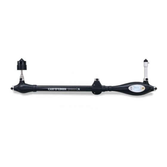
1 Introduction General PointX is a quick and accurate electronic measuring system. The PointX measuring system consists of: • A lightweight hand held measuring arm • Measuring tubes, magnetic attachment device and adapters • Vision2 PointX software with access to Car-O-Data, the worlds largest vehicle database 45929, EN - rev. - Page 8 A lightweight telescopic electronic measuring arm [1] made of composite materials forms the main component of the system. The PointX measuring arm has built in inclinometer for automatic level adjustment and built in laser for measuring distance between measuring points.
- Page 9 The PointX Electronic Measuring System is delivered in a durable lightweight case which contains the measuring arm, measuring tubes, magnetic attachment, adapters, extension device and batteries. The case also contains Quick Guide, Software CD, Car-O-Data DVD and Bluetooth adapter. Figure 1.2 The PointX case with complete measuring kit.
-
Page 10: Marking
Marking The name plate is placed according to the picture below. Figure 1.4 The PointX name plate 1.2.1 Matching serial numbers on measuring arm and measuring arm extension name plates To achieve correct measuring results, the measuring arm and measuring arm extension are factory calibrated together, therefore their serial numbers must match. -
Page 11: Vision2 Pointx Measuring Software
Vision2 PointX measuring software Vision2 PointX contains the original version of the measuring software. Vision2 PointX automatically checks for updates every week if you are a registered Car-O-Data internet user. As a Car-O-Data internet user you can also manually update Vision2 PointX. -
Page 12: Car-O-Data Vehicle Database Via Internet
Car-O-Data vehicle database via Internet Car-O-Data is the worlds largest vehicle database containing Car-O-Liner index with DataSheets for more than 8 000 vehicle models available for PointX measuring system. To use the Car-O-Data database you need to be a Car-O-Data subscriber. -
Page 13: Safety
Great effort has been placed on the design and manufacture of the PointX Electronic Measuring System so that it will comply with all applicable safety aspects for this type of equipment. During operation and other work, it is always each individual’s responsibility to consider:... -
Page 14: Warnings And Important Notices
Warnings and important notices The following types of safety signs are used on the equipment and in Car-O-Liner’s instruction manuals: PROHIBITED – Prohibits behaviour that can cause injury. COMMAND – Prescribes a specific responsibility or action. WARNING – Warns of risks for personal injuries and or damages to equipment. - Page 15 WARNING: Laser radiation when open. Do not stare into beam. Class 1 laser product*. IMPORTANT: Do not open the PointX measuring arm. All service must be carried out by authorized Car-O-Liner service personnel. IMPORTANT: It is the responsibility of the owner (user) to ensure that the equipment has been installed as specified in the instructions provided.
- Page 16 Accuracy will suffer if these items are not properly secured. IMPORTANT: The PointX measuring arm should be kept clean to allow smooth operation of the measuring arm. IMPORTANT: The PointX measuring arm should be kept away from all welding sparks and slag.
-
Page 17: Installation
Insert 2 AA batteries in the battery compartment on the back of the measuring head, see picture below. Car-O-Liner recommends rechargeable batteries. Battery cover latch is released by hand. The PointX measuring arm is now ready to use. Figure 3.1 Insert the batteries. -
Page 18: Installing Vision2 Pointx Software
Installing Vision2 PointX software Place the Vision2 PointX installation CD into the CD-drive and click on the Install Vision2 PointX. Then follow the on screen instructions. For registration, see Vision2 PointX Quick Guide. NOTE: Your computer needs internet access! Pairing of Bluetooth The PointX measuring arm communicates with the PC via Bluetooth. -
Page 19: Operation
4 Operation PointX measuring arm Before you begin using PointX measuring arm and Vision2 PointX, be sure to read the instructions in this Instruction Manual and that you understand them. The equipment is inspected and checked prior to leaving the factory to guarantee consistent quality and maximum reliability. -
Page 20: Turning On/Off The Pointx
2. Turn off by pressing and holding the "Target button" for about 4 seconds, when in Start menu. A "Shutting down" message appears and the PointX will be completely turned off after a few seconds. NOTE: The PointX will power off automatically after 10 minutes of inactivity to increase battery life time. - Page 21 The PointX measuring arm is easy to operate. The basic principles for operating the measuring arm is described below. For more extensive information regarding how to perform measuring, see section 4.4-4.5 Measuring methods. Place the magnetic attachment (or measuring adapter) on a symmetrical, undamaged reference point.
-
Page 22: Display Functions For Measuring
2. Display showing menus and measuring information. 3. "Target button" for registration of measuring value and on/off function. Normal measuring Start the PointX by pressing the "Target button" The Start menu appears. Measure mode is default. 45929, EN - rev.6, 2019-03... - Page 23 Start measuring by pressing the "Target button" The measuring view below appears. Here you will get information about: a) Measured distance in mm. b) Identification of current distance (1-5 in a measuring situation). c) Recommended measuring tube for reference point. d) Recommended measuring tube for measuring point.
- Page 24 To activate "Continuous measuring" press and hold for about 2 seconds. In this mode the measuring value changes "live" when the measuring arm length is altered. To register measured value, press . "Continuous measuring" is now automatically deactivated. Return to Start menu by pressing button.
- Page 25 Return to Start menu by pressing button. For changing of Measuring point measuring tube, toggle to "MeasPoint Tube" with button. Select desired measuring tube with button. Press to activate measuring mode. For information about the software version and serial number, toggle with button to "About", activate with and the view...
- Page 26 1. Return to Start menu by pressing button, toggle with button to "Settings", activate with and choose between: 2. “Time out”, to set automatic PointX turn off time. 3. “Screen offset”, to adjust the display interface position. 45929, EN - rev.6, 2019-03...
- Page 27 4. “Rotation ON/OFF”, choose “ON” and the display can be rotated 180º which enables you to measure upside down. 5. “Language”, to choose language. 6. “Close”, to close Settings menu and return to Start menu. 45929, EN - rev. 6, 2019-03...
- Page 28 Point-To-Point (P2P) Standard measuring The only information in Point-To-Point Standard body measuring that differs from the one in Normal measuring is the Distance ID. Point-To-Point uses a combination of measuring view and point name. In the example below the measured distance is point A to B in the Engine compartment (EC).
- Page 29 Absolute measuring In Absolute measuring you measure parallel distances or cross measurements, so the distances come in pairs. The example below identifies the current distance to measure, 1-1, the first distance of a pair (1-1 and 1-2). 45929, EN - rev. 6, 2019-03...
- Page 30 Display status bar 1. Battery status low. 2. No communication between measuring arm and PC. 45929, EN - rev.6, 2019-03...
- Page 31 2. Shake warning icon turns green when measuring arm is held sufficiently stable for measuring. NOTE: Should any display error code appear (for example “E002”), contact Support! *Applies to PointX II measuring arm only. 45929, EN - rev. 6, 2019-03...
-
Page 32: Measuring Tubes
4.1.3 Measuring tubes The measuring system consists of a wide selection of measuring tubes. The tubes have different lengths to suit all measuring situations. For best results, use shortest tube possible while allowing sufficient working height under the vehicle. The measuring tubes are fitted according to the description below: Turn the knob counter clockwise to open the socket (or to release a measuring tube). -
Page 33: Measuring Tube Fitting Configurations
Figure 4.3 PointX measuring tubes. NOTE: For correct measuring result, make sure that the measuring tube is pressed into the bottom of the socket and that the knob is properly tightened. 4.1.4 Measuring tube fitting configurations To achieve ultimate conditions in every measuring situation the measuring tubes can be fitted in various configurations. -
Page 34: Magnetic Attachment
Magnetic attachment device. 4.1.6 Measuring adapters (sockets and tips) The PointX measuring adapter system includes various sockets and tips. The sockets and tips snap into the top of the measuring tubes. Measurements are printed on each adapter. For complete chart of measuring adapters, see chapter 15 Spare parts. -
Page 35: Measuring Arm Extension
4.1.7 Measuring arm extension The PointX measuring arm can be extended in order to reach further if the distance between starting point and measuring point is longer than the fully extended measuring arm. Insert the extension into the socket on the further end from the measuring head. -
Page 36: Battery Change
4.1.8 Battery change The electronic circuit of the PointX measuring arm is powered by 2 AA batteries. It is recommended that both batteries should be replaced and that the old batteries should be disposed of in accordance with local hazardous waste disposal regulations. -
Page 37: Pointx Usb Slot
4.1.9 PointX USB slot The PointX measuring arm has a USB slot to be used only for upgrading and reprograming of the measuring arm software. Not to be used during normal operation! NOTE: Upgrading and reprogramming of the measuring arm must be carried out by authorized Car-O-Liner service personnel. -
Page 38: Open Pointx Software And Start To Work
Self instructive tab system for easy navigation.Each tab is described in section 5.1 The Vision2 PointX Main Tab System. 1. Click on the Vision2 PointX icon on the desktop. 2. Vision2 PointX starts up and the Start menu (Home tab) appears. 45929, EN - rev.6, 2019-03... -
Page 39: Open An Existing Workorder
4.2.1 Open an existing Workorder When continuing to work on an existing Workorder: 1. Click on the "Existing Workorder" button. 2. Select an ongoing Workorder. Click on to delete a Workorder. 3. Add info such as license number, mileage, notes etc. 45929, EN - rev. -
Page 40: Create A New Workorder
4.2.2 Create a new Workorder Before you start to do repair work on a car you have to create a new Workorder: 1. Click on the "New Workorder" button. 2. Fill in the Workorder name and create a Workorder. 3. The "Workflow Guide" guides you trough the work process. Deactivate by clicking (4). -
Page 41: Find And Download A Datasheet
4.2.3 Find and download a DataSheet 1. Double click on the required vehicle make. 2. Select subgroup by double clicking on for example "CARS". 3. Click on the required model and then click on the "Download DataSheet" icon. icon (4) indicates downloaded DataSheet. 5. -
Page 42: Search For A Datasheet
1. Type, for example, make, model or body code. Click on the magnifying glass icon. In the Car-O-Liner Index there are four different symbols in front of the model A blue @sign indicates that the data sheet is not stored locally on the hard drive. -
Page 43: View List Of New (Recently Released) Datasheets
4.2.5 View list of new (recently released) DataSheets 1. Click on "View new DataSheet" icon. 2. Click on the "Download DataSheet" icon to download selected DataSheet from DataSheet index. 45929, EN - rev. 6, 2019-03... -
Page 44: Preparation/Set Up Of The Vehicle
4.2.6 Preparation/set up of the vehicle Under the "Preparation" tab you will find all the necessary information about how to prepare and set up the vehicle for measuring. The information includes what clamps to use and positioning of the clamps. 1. - Page 45 For more extensive information regarding preparation/set up of the vehicle, see section 5.4 The Preparation tab. 45929, EN - rev. 6, 2019-03...
-
Page 46: Center And Measure The Vehicle
4.2.7 Center and measure the vehicle In sections 4.4 - 4.7 you will find all the necessary information on how to perform Centering and Measuring of the vehicle. "Centering" is a method to calculate tilting of the vehicle, and is done in an undamaged area of the vehicle. - Page 47 3. Select an undamaged reference point in the data sheet. When selected, the reference point will be marked with a black circle Reference point information in box, marked with black frame [4]. Click "Next" button to continue to next step 5.
- Page 48 9. Measure centering distances. Distances are marked with blue lines. Centering is now completed if centering is correct, see “Centering Diagnose Symbols, page 56. Click “Next” to proceed to Measuring situation No. 1. Measuring values 10. Select a reference point in the data sheet. When selected, the reference point will be marked with a black circle and a corresponding reference point will automatically appear on the opposite side of...
- Page 49 12. Select a measuring point in the data sheet. When selected, the measuring point will be marked with a green circle and a corresponding measuring point will also appear. 13. Measuring point information in box, marked with green frame. 14. Measure distances in the sequence indicated by the numbers in the measuring situation (current distance marked with blue).
-
Page 50: Documentation Of The Vehicle
Documentation of the vehicle Under the "Documentation" tab you will find the "Print protocol" function which enables you to print your requested reports or save to "Workorder folder". 4.3.1 Print protocol 1. Click on requested reports. 2. Click on “Add photos”-button to add photos to the report (see 5.6.3 Add photos to the report). -
Page 51: Print Preview
4.3.2 Print preview 6. The "Print preview" function enables you to check the print-outs before printing, select number of reports per print-out, etc. 45929, EN - rev. 6, 2019-03... -
Page 52: The Centering And Normal Measuring Method
DataSheet and to follow the "Parts In" or "Parts Out" adapter information. It is also very important to measure the points in the same way as shown on the DataSheet, and in the way they are selected in Vision2 PointX display. 45929, EN - rev.6, 2019-03... -
Page 53: The Standard Centering Method
4.4.2 The Standard centering method 1. Select an undamaged reference point in the data sheet. When selected, the reference point will be marked with a black circle Click "Next" button to continue to next step 2. Select a centering point in the data sheet. When selected, the centering point will be marked with a yellow circle 3. - Page 54 NOTE: For best centering accuracy, the width between the reference points and the lengths to the centering points should be between 600 - 1300 mm. Using points under the center of the vehicle is recommended. 45929, EN - rev.6, 2019-03...
-
Page 55: The Advanced Centering Method (Default Setting)
4.4.3 The Advanced centering method (default setting) To get a more accurate height calculation, it is recommended that you perform the advanced centering method. This is the default setting. 1. Select an undamaged reference point in the data sheet. When selected, the reference point will be marked with a black circle and a corresponding yellow centering point... - Page 56 Cross measuring Cross measuring is an additional control step to make sure the centering points are not damaged. This step is optional, you can move on to measuring by clicking on the “Next” button. 45929, EN - rev.6, 2019-03...
- Page 57 Centering Diagnose Symbols: Advanced centering: Green distance [a]: Measured distance within Centering Stop Limit. Red distance [b]: Measured distance outside Centering Stop Limit. Green centering symbol [c]: Angle approved. Red centering symbol [d]: Angle deviates too much Standard centering: from angle measured in opposite direction.
-
Page 58: The Normal Measuring Method
4.4.4 The Normal measuring method Always consider vehicle safety features and design when selecting measuring points, making sure that the points can be reached and measured. You can create up to 6 measuring situations. 1. Select a reference point in the data sheet. When selected, the reference point will be marked with a black circle and a corresponding reference point will automatically appear on the opposite side of the vehicle. - Page 59 NOTE: The point's values are automatically stored and/or updated in the memory of the PC and it can be obtained whenever needed. NOTE: The length of the magnetic attachment corresponds to the length of the 100 mm measuring tube fitted with a 25 or 35 mm tip. 45929, EN - rev.
-
Page 60: The Point-To-Point (P2P) Standard Measuring Method
DataSheet. The PointX can be used for measuring without DataSheet. The measuring arm is then used as a tape measure for parallel or cross measuring. The PointX measuring arm features "Continuous measuring"... - Page 61 1. Select Point-To-Point (P2P) Standard measuring view from dropdown menu. 2. Click on a Measuring view button to activate a specific view. Active view is marked by a black frame. 3. Appropriate measuring arm information is shown in the information box and in the measuring arm display.
- Page 62 Measuring values can be registered manually (for example with tape measure) if measuring points are out of reach for the PointX measuring arm, if distance between measuring points is below 300 mm or due to obstacles. 1. To register measuring value manually, double click on distance and type in value.
- Page 63 Point-To-Point measuring can also be performed on lower body. 1. Select Lower body measuring mode. 2. Perform the same measuring method as on upper body. Ball joint measuring For some vehicles, P2P measuring can be used to measure distances on suspension ball joints. 1.
-
Page 64: Point-To-Point Standard Measuring Adapters
4.5.1 Point-To-Point Standard measuring adapters NOTE: Depending on the distance to be measured and the geometry of the car body, you must select one of the following measuring adapters when working in P2P mode: M101-25, M106 or M107. If any other adapter is used, the measured distance may be incorrect. - Page 65 The M101-25 adapters are also used when measuring on screws, for example in the engine compartment, as seen in the picture below. Figure 4.9 Measuring tube configuration for the M101-25 adapters. Adapters M106 The M106 adapters are used when measuring from edge to edge, for example a door opening.
- Page 66 Adapters M107 The M107 adapters are used when there are obstacles in the distance to be measured, or when the distance to be measured is too short to use the M106 adapters/measuring tube configuration. Place the M107 adapters according to the picture below. NOTE: The tips of the M107 adapters must align.
-
Page 67: Point-To-Point Measuring Point Descriptions
4.5.2 Point-To-Point measuring point descriptions The Point-To-Point measuring point symbols are shown in the DataSheets and in the software information box. In the table below you can see the meaning of the symbols. Description Symbol Hole Square hole Oval hole Head to rail Washer to head Washer to stud... - Page 68 Torx srew Middle of oval hole Center of arc 45 Center of arc 135 Center of arc 225 Center of arc 315 Check Strap hinge mounting bolt Rear edge of wiring loom hole Center of light switch hole Bottom screw of striker plates 45929, EN - rev.6, 2019-03...
- Page 69 Top screw of striker plate Center of head of striker pin Center W/S screw Left screw of striker plate Seam at edge of sill plate Center post trim bolt Corner Inner Seam Outer Seam Notch 45929, EN - rev. 6, 2019-03...
- Page 70 Center of fender bolt Center hinge bolt Center of front screw Front W/S Moulding screw Center rear hinge bolt Upper hinge bolt Bottom hole of striker plates Top hole of striker plate Check strap hinge mounting hole Lower hinge bolt 45929, EN - rev.6, 2019-03...
- Page 71 Cross marking, unidentified point object Center of check Strap hinge pin Check strap hinge hole Center bottom hinge bolt Check Strap hinge upper mounting bolt Check Strap hinge lower mounting bolt Striker pin hole Check strap hinge upper hole Check strap hinge lower hole Outer edge of post below door hinge 45929, EN - rev.
- Page 72 Ball joint Six sided hole Right screw of striker plate 45929, EN - rev.6, 2019-03...
-
Page 73: The Point-To-Point (P2P) Advanced Measuring Method
The Point-To-Point (P2P) Advanced measuring method The Point-To-Point Advanced measuring method is a method used to measure lower body distances from one point on the vehicle to another and compare them to reference values in the DataSheet. P2P Advanced is a flexible way of measuring as you are free to choose which distances to measure using existing measuring points, while in P2P Standard the distances are preset and cannot be changed. - Page 74 1. Select Point-To-Point (P2P) Advanced measuring view. 2. Select a reference point in the data sheet. When selected, the reference point will be marked with a black circle and a corresponding reference point will automatically appear on the opposite side of the vehicle. 3.
-
Page 75: The Absolute Measuring Method
The Absolute measuring method Absolute measuring is used when no DataSheet is available or if you want to measure a point that is not included on the DataSheet. When using Absolute measuring, you may choose any measuring points. The vehicle can either be measured using Parallel measuring or Cross measuring. - Page 76 1. Select Absolute measuring mode. 2. Measuring points can be dragged around the screen to register their position. 3. Appropriate measuring arm information is shown in the information box and in the measuring arm display. 4. Measure and register the 1-1 distance by pressing the "Target button"...
- Page 77 Absolute measuring can also be performed on lower body. 1. Select lower body measuring mode. 2. Perform the same measuring method as on upper body. NOTE: Depending of the distance to be measured and the geometry of the car body, you must select one of the following measuring adapters when working in Absolute measuring mode: M101-25, M106 or M107.
-
Page 78: Close Vision2 Pointx
Close Vision2 PointX 1. Close the Vision2 PointX software by clicking on the X icon in the upper right corner. 45929, EN - rev.6, 2019-03... -
Page 79: Key Functions
5 Key functions The Vision2 PointX Main Tab System Vision2 PointX Tab System you can navigate through the work In the process and you can also acquire a wide selection of information. The Main Tab System "workflow" guides you through the work process, but you can easily navigate manually by using the forward/return buttons (6). -
Page 80: The Home Tab
The Home tab Under the Home tab you will find the options "Existing Workorders" or "Create new Workorder". 5.2.1 Existing Workorder When continuing to work on an existing Workorder. Existing Workorder 5.2.2 Create a new Workorder When starting a new job you must first create a new Workorder. Create new Workorder 45929, EN - rev.6, 2019-03... -
Page 81: The Workorder Tab
The Workorder tab Each Workorder form gives you information about the customer; the Insurance Company involved and allows you to make a specification of the work performed on the vehicle. 5.3.1 Workorder list Recent Workorders Workorder list Shows all Workorders saved in the Workorder data base. -
Page 82: Customer Information Sub Tab
5.3.3 Customer information sub tab 2. Here you can enter information about the customer. Customer list Shows all customers saved in the customer data base. Add new customer by clicking on "Add new customer" button underneath the customer list. 5.3.4 Insurance information sub tab 3. -
Page 83: Car-O-Liner Index
5.3.5 Car-O-Liner Index The Car-O-Liner Index includes all DataSheets stored in the Car-O-Data database. To select a DataSheet, see section 4.2.3 ”Find and download a DataSheet". Index list Favorites list Add to favorites list Click on the tabs to switch... - Page 84 Subgroup Body code Year Shows the selected Shows the body Shows the Shows the type of vehicle e.g. code of the manufacturing DataSheet number "car" or "SUV". selected vehicle years of the of the selected (if available). selected vehicle. vehicle. Type Shows the Make...
- Page 85 Hard top 6 cylinder V-engine Independent rear susp. 8 cylinder V-engine Liftback 10 cylinder V-engine Light commercial 12 cylinder V-engine Left hand drive Wankel engine Long Wheelbase Table 5.1 Type codes for Car-O-Liner Index 45929, EN - rev. 6, 2019-03...
-
Page 86: Download Datasheet
5.3.6 Download DataSheet 1. To download a DataSheet, click on the required model and then click on the "Download DataSheet" icon. icon (2) indicates downloaded DataSheet. Update index list. Click to update index list View new DataSheets Click to view newly released DataSheets from Car-O-... -
Page 87: Search Function
Search function The search function is an alternate method of finding a DataSheet in the Car-O-Liner Index. Type in a DataSheet number or "free text" for example car make or model combined with year. 1. Click in the search field and type in requested vehicle information. -
Page 88: The Preparation Tab
The Preparation tab Under the Preparation tab you will find the following functions: "Select vehicle on support/on wheels", "Select Engine In/Out" and "Clamping information". 5.4.1 Vehicle on support or on wheels 1. Chose if the vehicle is on support or on clamps. 5.4.2 Engine In or Out 2. -
Page 89: Info Center
5.4.3 Info center Clamping mode “Setup” subtab Here you find information about where to attach clamps during vehicle setup. Yellow dot [1] displays front attachment point. Blue dot [2] displays rear attachment point. Multimedia presentation* Click on yellow or blue dot to Clamping information view multimedia presentation of Click on yellow/blue dots... - Page 90 Lifting mode* Lifting accessory picture Click on lifting accessory [10] to view a picture of it. Recommended lifting points Multimedia presentation Click on arrows [8] for photos of Click on arrow [8] or box [9] to recommended lifting points. Click view multimedia presentation of on boxes [9] to toggle lifting point lifting accessories assembly.
-
Page 91: The Measuring Tab
The Measuring tab The measuring methods available in the PointX software are Normal-, Absolute- and Point-To-Point (P2P) measuring. 5.5.1 The Normal measuring view Click on icon to zoom explanatory drawing. Shortcut to “Tolerance settings” Centering and measuring Normal measuring mode... -
Page 92: The Point-To-Point (P2P) Standard Measuring View
5.5.2 The Point-to-point (P2P) Standard measuring view P2P Standard measuring mode Target button Reference point Measured information box distance marked with black frame. Displays selected measuring point, tube, adapter and configuration. Measuring view Measuring point information box marked with green Measuring point frame. -
Page 93: The Point-To-Point (P2P) Advanced Measuring View
5.5.3 The Point-to-point (P2P) Advanced measuring view Click on icon to zoom explanatory drawing. Shortcut to “Tolerance settings” Measuring workflow P2P Advanced information measuring mode Target button Reference point information box marked with black frame. Displays selected Reference and measuring point, measuring points tube, adapter and Black circle:... -
Page 94: The Absolute Measuring View
5.5.4 The Absolute measuring view Target button Absolute measuring mode Measuring point information box Displays measuring arm configuration, tubes and adapters. Movable measuring points Drag around the screen to register their position. Add your own photos (optional) Add your own notes (optional) Upper body/Lower body Measuring point values field... -
Page 95: Measuring Information In Lower Statusbar
5.5.5 Measuring information in lower statusbar Centering Workorder On support/ No communication approved Shows name of On wheels between the measuring – green icon. Click on the icon active Workorder. arm and the PC. Not approved to toggle between – red icon. On clamps and On wheels. -
Page 96: Tolerance
5.5.6 Tolerance For tolerance setup, see section 9.3 Vision2 PointX Setup - Measuring. You can also use a shortcut to “Tolerance settings”, see picture at the bottom of this page. When setting Measuring - Presentation - Graphical presentation is selected (as seen in the picture below), red arrows appear on the Symbolic DataSheet where the measuring values are out of tolerance. -
Page 97: The Documentation Tab
The Documentation tab Under the "Documentation" tab you will find the "Print protocol" function which enables you to print out your requested reports. Toolbox icon for “Documentation settings”, see 5.6.2 Documentation settings. E-mail the report Add photos to the report Green checkmarks marks selected reports for printing and saving... -
Page 98: Print Preview
5.6.1 Print preview Select number (1-5) of reports Print Printer set up (pages) per print out. Check the print-outs before printing. For printer settings, see chapter 6 Settings. 45929, EN - rev.6, 2019-03... -
Page 99: Documentation Settings
5.6.2 Documentation settings In ”Documentation settings” (in the “Toolbox”) you can set Tolerance. The settings made in ”Documentation settings” do not affect the Tolerance set in the Measuring mode. 45929, EN - rev. 6, 2019-03... -
Page 100: Add Photos To The Report
5.6.3 Add photos to the report 1. In the “Add photos” step you can add photos to the documentation if required. The photos are saved to the current workorder. 2. Click the “Add photo” button and choose a photo on your computer. 3. -
Page 101: E-Mail The Report
5.6.4 E-mail the report 1. In the “E-mail” step you can send and e-mail and attach saved reports and photos if required. 2. Click in the checkbox next to each photo to attach it to the e-mail. 3. When your e-mail is complete, send it by clicking the “Send e-mail” button. -
Page 102: Settings
6 Settings You will find all the necessary settings for the Vision2 PointX software in the black upper bar. The setting options are available all the time. In the given example below the settings for model translation in "Index list" is described. -
Page 103: Tools
Backup workorder To help ensure that you don´t lose your files, you should back them up regularly. In Vision2 PointX you can set up automatic backup or manually back up files by following the instructions in this section. To activate the Backup function, select “Backup” under the Tools tab. - Page 104 Backup workorder key functions: 1. Active workorder information. 2. Workorder list on your computer sorted by name or date. 3. Workorders to be backed up. 4. Click in the “Backup” field. Workorders are now transferred from computer to backup [5]. 5.
-
Page 105: Help Functions
8 Help functions Under “Help“ in the black upper bar you will find all the necessary help functions for the Vision2 PointX software. The Help functions are available all the time. The available help functions for Vision2 PointX software: About Vision2 PointX – CD key and Machine ID codes Instruction manual –... -
Page 106: Vision2 Pointx Setup
To start Vision2 PointX Software Setup go to: For Windows 8 and 10: Start > Vision2 PointX > Vision2 PointX Setup For XP, Vista and Windows 7: Start > All programs > Vision2 PointX > Utilities > Vision2 PointX Setup NOTE: Before starting Vision2 PointX Software Setup, please exit and close Vision2 PointX Software. -
Page 107: Vision2 Pointx Setup > Centering
Vision2 PointX Setup > Centering The “Centering“ menu is used to set Number of Points to use for Centering. Number of Points to use for Centring Select “Standard” or “Advanced” Stop limit Limit for distance deviation during centering. Vision2 PointX Setup > Measuring The “Measuring“... -
Page 108: Vision2 Pointx Setup > Language
Vision2 PointX Setup > Print The “Print“ menu is used to change the Car-O-Liner logotype on “Vision2 PointX Software Report” and in the “Print outs“. Logotype Used to select a logotype. -
Page 109: Vision2 Pointx Setup > Export
Vision2 PointX Setup > Backup The “Backup function“ menu allows the user to transfer the Work orders on to a USB or to the hard drive. You can also set Vision2 PointX Software to prompt for backup at regular intervals. -
Page 110: Vision2 Pointx Setup > Mail
Vision2 PointX Setup > Mail The “Mail“ menu is used to setup e-mail account used by Vision2 PointX Software. Request the appropriate information from the company system administrator before you set up the e-mail account. Host name Enter a host name. -
Page 111: Vision2 Pointx Diagnose
To start Vision2 PointX Diagnose go to: For Windows 8 and 10: Start >Vision2 PointX > Vision2 PointX Diagnose. For XP, Vista and Windows 7: Start > All programs > Vision2 PointX > Utilities > Vision2 PointX Diagnose 10.1 Vision2 PointX Measuring System Diagnose >... -
Page 112: Vision2 Pointx Measuring System Diagnose > Version
10.2 Vision2 PointX Measuring System Diagnose > Version The “Version“ menu gives information about version numbers and serial numbers, etc. 45929, EN - rev.6, 2019-03... -
Page 113: Vision2 Pointx Measuring System Diagnose > One Point Check
10.3 Vision2 PointX Measuring System Diagnose > One Point Check Perform “One Point Check“ to check if measuring arm is measuring correct. How to perform “One Point Check”, see bottom of this page. “One Point Check”: 1. Register two measuring points. -
Page 114: Maintenance
Car-O-Liner service personnel. 11.1 Calibration PointX is a measuring device and should be handled with care. Please contact your Car-O-Liner distributor for questions regarding maintenance and calibration. Car-O-Liner recommends that the PointX is calibrated once a year. -
Page 115: Cleaning
11.2 Cleaning PointX is a measuring device and should be handled with care. The PointX should be cleaned with a dry or lightly damped cloth. IMPORTANT: No solvents, oils, lubricants, detergents or liquid should be exposed to the PointX measuring arm. -
Page 116: Troubleshooting
12 Troubleshooting The Troubleshooting schematic in this chapter (section 9.2) is a useful tool when tracing problems with Vision2 PointX and Car-O-Data. The Troubleshooting schematic presents the most common problems and their possible causes. IMPORTANT: Do not open the PointX measuring arm. All service must be carried out by authorized Car-O-Liner service personnel. -
Page 117: Checklist
12.1 Checklist If you find the instructions in the checklist below insufficient, please contact your Car-O-Liner distributor. What version of Vision2 PointX is installed on the computer? ________________________ Version of Car-O-Soft Vision2 PointX What version of Car-O-Data Update is installed on the computer? - Page 118 The information in points 4-9 are required only if the problem concerns faulty measuring values. Which measuring points are not correct? ________________________ Faulty measuring points What is the difference in height, length and width between the correct ________________________ DataSheet measuring points and the Height faulty points being measured? ________________________...
-
Page 119: Troubleshooting Schematic
If the suggested actions below still do not solve your issue, please contact you Car-O-Liner distributor. Bluetooth Communication Issues Unable to find/connect to the 1. Make sure that PointX is on. PointX Bluetooth device 2. Try to locate PointX using another PC or Device with Bluetooth. - Page 120 Use the included extension cable to ensure a “free line of sight” between the PointX and the USB Bluetooth dongle. Do not have the Bluetooth mounted on the back of a desktop PC. Measuring issues...
- Page 121 Both during measuring and especially during centering, make sure that: 1. You use the correct tubes and that they are fitted properly in the sockets. 2. You measure between the correct points. 3. You measure in the right direction and measure front-to- back instead of back-to-front or left-to-right instead of right-to- left.
- Page 122 Battery life time issues PointX can be used with any AA or LR6 batteries, both standard 1,5V and rechargeable 1,2V. High quality alkaline batteries or high power rechargeable batteries are recommended. Car- O-Liner recommends using high quality/high power rechargeable batteries together with a charger...
-
Page 123: Dismantling And Salvage
Mechanical components, electrical components, plastic, composite materials, steel and aluminium should be sorted for material recycling. 13.1 Battery The battery in the PointX measuring arm must be recycled or disposed of properly. IMPORTANT: For the sake of the environment, it is important that the equipment is dismantled in an environmentally friendly way. -
Page 124: Technical Specifications
14 Technical Specifications 14.1 Computer requirements The Vision2 PointX minimum system requirements are: • Intel® Pentium® 4 (2.4 GHz processor), Intel Core Duo processor or newer, AMD XP2500+ or newer AMD processor • 1GB RAM (32-bit) or 2GB RAM (64-bit) •... -
Page 125: Pointx Measuring Arm
- Colour display Quality certificate, ISO9001, ISO14001 Car-O-Liner Group AB NOTE! PointX is an individually calibrated measuring device meant for estimating purposes. Mechanical tolerances as offsets and angular displacements of the device are compensated for in the calibration process by the software. -
Page 126: Software Versions
Vision2 PointX and Car-O-Data is updated via Internet. Each time the software is updated, the version number of Vision2 PointX is increased. The actual version number of Vision2 PointX can be found in "About Vision2 PointX", see chapter 8 Help functions. -
Page 127: Spare Parts And Accessories
15 Spare parts and accessories The spare parts for the PointX Electronic Measuring System are listed in the tables below. NOTE: Use only genuine Car-O-Liner spare parts. To order, contact your local Car-O-Liner distributor. 15.1 Measuring tubes M701-25 M701-60 M701-100... -
Page 128: Measuring Adapters
15.2 Measuring adapters M100-8 M100-10 M100-12 M100-14 M100-15 M100-16 M100-17 Adapter Ø8 Adapter Ø10 Adapter Ø12 Adapter Ø14 Adapter Ø15 Adapter Ø16 Adapter Ø17 30200 30208 30209 30210 30205 30211 30206 M100-18 M100-19 M100-20 M100-21 M100-22 M100-24 M100-25 Adapter Ø18 Adapter Ø19 Adapter Ø20 Adapter Ø21... - Page 129 M100-26 M100-28 M101-25 M101-35 M101-60 M106 Adapter Ø26 Adapter Ø28 Stud Ø25 Stud Ø35 Stud Ø60 Adapter 30216 30217 30198 30199 30241 45616 M107 M104 M105 M213 Adapter Adapter Magnetic attachment Adapter device with pin bracket 45617 30227 45029 48435 45929, EN - rev.
-
Page 130: Workshop Solutions
15.3 WorkShop Solutions The PointX measuring arm, measuring tubes and adapters can easily be fitted to the flexible WorkShop Solutions wall section system. To order, contact your local Car-O-Liner distributor. Figure 12.1 WorkShop Solutions wall section system. 45929, EN - rev.6, 2019-03... -
Page 131: Wsw90 Tool Wagon
15.4 WSW90 Tool wagon The PointX measuring arm, measuring tubes and adapters can easily be fitted to the versatile WSW90 Tool wagon. To order, contact your local Car-O-Liner distributor. Figure 12.2 WSW90 Tool wagon. 45929, EN - rev. 6, 2019-03... - Page 132 Tool holder Ø39 mm 36825 Tool holder Ø25 mm 30470 Clipholder, small Ø15 mm 30482 Bracket / Konsol L=610 30475 Decal PointX WSS L=396 45759 Decal PointX WSW90 L=285 45760 Edge Protection Profile L= 730mm 45361 45929, EN - rev.6, 2019-03...
- Page 133 Alignment Processes to the Automotive Industry, including Technical Development, Training and Service. Over 55 000 Car-O-Liner Collision Repair Systems are in use worldwide. Car-O-Liner runs operations of its own in Scandinavia, USA, UK, France, Germany, Thailand, India and China and sells through local distributors in more than 60 countries.
Need help?
Do you have a question about the PointX and is the answer not in the manual?
Questions and answers