Table of Contents
Advertisement
Quick Links
CW-SYS WIRELESS DRIVEWAY SYSTEM INSTRUCTIONS
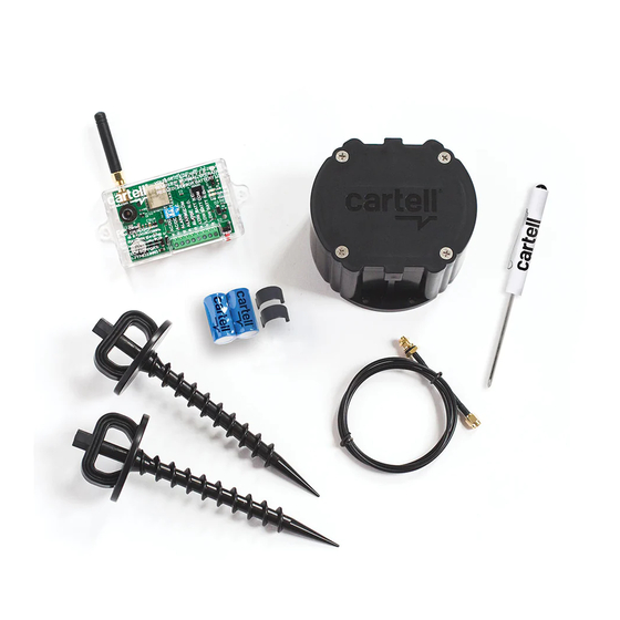
1. WHAT'S IN THE BOX
1. SENSOR "PUCK"
2. INTEGRATOR
3. AUGER SCREWS (2)
4. CR123A BATTERIES WITH
BATTERY CLIPS (2)
5. 3' (1 m.) COAXIAL CABLE
6. TERMINAL BLOCK
SCREWDRIVER
OPTIONAL
• 12VDC power
supply
(Part #CW-PSU)
2. SERIAL NUMBER
IA
and on product box. When calling to talk about your product, please have one
of these numbers handy.
PRODUCT
CODE
3. INSTALLING BATTERIES/LOW BATTERY
1. Use CR123A
4. PAIRING
YOUR SYSTEM HAS BEEN PAIRED AT FACTORY.
THESE DIRECTIONS APPLY WHEN PAIRING
ADDITIONAL UNITS
You can pair up to 10 pucks with unlimited number of Integrators
Pairing
1. Bring sensor close to Integrator and
power up Integrator
(see #10 below).
2. Push pairi
(will stay in pairing mode 30 minutes).
ON AN OBJECT
IN THE GROUND
• Use stable
object
• Put logo parallel to drive
• Use 4 deck
• Put just below surface
screws for
fastening
• Auger screws secure puck
• Do not cover puck lid
• Pack dirt/grass around
puck
min.
• Keep puck lid clean
6"- 8"
WARNING: KEEP LID FREE OF DIRT, GRASS, SNOW, & ALL DEBRIS AT ALL TIMES TO ALLOW RADIO SIGNAL TO TRANSMIT!
1
2
4
3
5
YEAR
SERIAL
MADE
NUMBER
LOW BATTERY
in sensor, Integrator will "chirp"
and its LED will blink RED.
When hooked to external
system's zone inputs (see #10
below), program what you desire
REPLACE BOTH BATTERIES.
DO NOT USE RECHARGEABLES.
3. Power down
& power up
sensor by un-
installing and
re-installing
(see #3 above).
4.
when paired and exit pairing mode
IN THE DRIVEWAY
Bore hole
4.5" x 2.75" deep
Use 4.5" masonry hole saw
Fill line
LOOP
Don't allow
SEALANT
sealant to
touch lid
or bosses
VERSION 1
5. TEST MODE FOR SENSOR PUCK
radio signal range (see #6 below).
2. The red LED will blink every second when in test mode
3. There will be an immediate transmission
6
Your system has a radio range of at least 350 feet or over 1000' line-of- sight.
Radio range depends on several variables:
How the puck is installed (in ground or above ground on post)
Obstacles blocking radio signal, such as soil, trees, foilage,
buildings, concrete, etc.
To test range:
3. Put sensor in test range mode (see #5 above).
4. Listen for Integrator to trigger. If it doesn't, move sensor closer to Integrator.
5. Be sure to test again with puck installed in ground (see #8 below).
6. You may need to add a repeater inside the home (see #9 below).
7. SETTING SENSITIVITY
ONLY ADJUST (LOWER) SENSITIVITY IF PUTTING IN MIDDLE OF
DRIVEWAY (see #8 below). IN ALL OTHER CASES USE DEFAULT.
SENSITIVITY ADJUSTMENT
HIGH (Default)
Detects vehicle going
5 MPH 12-14' away
1 & 2 in OFF position
MEDIUM
Detects vehicle going
5 MPH 6-8' away
1 ON & 2 OFF position
LOW
Detects vehicle going
5 MPH 2-4' away
1 & 2 in ON position
8. INSTALLING SENSOR PUCK
WARNING: SCREW HOLES IN PUCK WILL STRIP. DO NOT OVERTIGHTEN WITH
SCREW GUN OR TAKE IN & OUT REPEATEDLY. IF SCREWS ARE STRIPPED,
PURCHASE LONGER STAINLESS STEEL SCREWS, SUITABLE FOR PLASTIC.
The sensor puck can be installed in the driveway, in the ground or on an
immovable object (post, tree, etc.).
ON AN OBJECT
1. When range has been tested (see #6 above), seat lid securely on puck with
screws provided. Be careful not to strip screws with screw gun. There should be
no gap between lid and puck.
2. Find a tree, post, or other object directly beside the driveway.
3. Make sure the object is IMMOVABLE or false alarms will occur.
IN THE GROUND
1. When range has been tested (see #6 above), seat lid securely on puck with
screws provided. Be careful not to strip screws with screw gun. There should be
no gap between lid and puck.
2. Find a spot directly beside driveway.
3. Dig a hole big enough for puck and auger screws, allowing puck's lid to be
Pour
sealant
level with surface of dirt.
in hole,
then
install
If you fail to secure puck, lawn mowers, etc. will pull/suck it up.
puck.
5. Pack and tamp dirt around puck, ensuring lid is clean of dirt and all debris.
Do not
cover
IN FREE EXIT INSTALLATIONS, IF ANIMALSOR PEOPLE STEP ONSENSOR
lid or
bosses
PUCK INSTALLED IN THE GROUND, IT MAY TRIGGER THE GATE TO
with
OPEN. CONSIDER INSTALLING ON POST OR IN DRIVEWAY INSTEAD.
sealant.
IN THE DRIVEWAY
1. When range has been tested (see #6 above), seat lid securely on puck with
screws provided. Be careful not to strip screws with screw gun. There should be
no gap between lid and puck.
1/4"
2. Use a 4.5" diameter masonry hole saw to bore a hole for puck. Bore at least
2.75" deep so puck lid will be 1/4" below driveway surface (so it can't be pulled
up by snow plows, graters, etc.).
to put in
to put in
test mode
test mode
6. TESTING RANGE
NOTE: HIGHEST SENSITIVITY IS WITH
DIP SWITCHES IN THE
ON
1
2
ON
1
2
ON
NOTE: DIP SWITCH
1
2
COLOR MAY VARY
OFF
POSITION
Advertisement
Table of Contents

Summary of Contents for Global Access CW-SYS
- Page 1 CW-SYS WIRELESS DRIVEWAY SYSTEM INSTRUCTIONS VERSION 1 1. WHAT’S IN THE BOX 5. TEST MODE FOR SENSOR PUCK 1. SENSOR “PUCK” radio signal range (see #6 below). 2. INTEGRATOR 3. AUGER SCREWS (2) 2. The red LED will blink every second when in test mode 4.
- Page 2 “COM” or “OPEN” (use one) TERMINAL WHEN USING CW-SYS FOR FREE EXIT. 11. REPEATER MODE To increase radio range, it may be necessary to make the Integrator a repeater. If the signal from sensor puck is not reaching the Integrator: void the user’s authority to operate the equipment.
Need help?
Do you have a question about the CW-SYS and is the answer not in the manual?
Questions and answers