Table of Contents
Advertisement
Quick Links
Advertisement
Table of Contents

Summary of Contents for Inverter sMove
- Page 1 Installation instructions sMove Control unit www.inventer.de...
-
Page 2: Table Of Contents
The copyright to this document remains with the manufacturer. Rights to all content and images: © inVENTer GmbH 2022. System overview: sMove controller ..................7 Construction ........................8 All trademarks used in this document are the property of their respective manufacturers and are Function ......................... -
Page 3: User And Safety Instructions
Safety instructions Thank you for purchasing this high quality product from inVENTer! The installation instructions are part of your sMove control and must be available at all times (see www.inventer.de/downloads). When handing the system to a third party, the information regarding This section provides an overview of the basic safety precautions for safe and proper operation of access to the installation instructions must be handed over also. -
Page 4: System Overview: Smove Controller
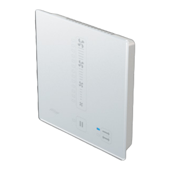
Avoid contact with sharp or pointed objects, e.g. rings. The sMove controller can be used either as a base control unit or with additional sensors • When using several ventilation devices controlled by several controllers, you must ensure that connected. -
Page 5: Construction
Construction sMove controller with connected external interface The sMove controller consists of a mounting plate for installation on the interior wall and a control The external interface is a bi-functional port on the back of the operating unit. It enables unit. -
Page 6: Electrical Connection
Output cable for switching power supply GND ( ┴ ) Black (for control voltages, see section 3.3: Electrical connections – jumpers). unit Rear view of sMove controller operating unit Electrical connection GND ( ┴ ) Controller operating voltage Black Controller operating... -
Page 7: Cabling
Connection terminal, 2-pole (external interface) If the sMove s8 is connected in conjunction with a flush-mounted switched-mode power supply, we recommend distributing the cables between the controller and the fan in a separate mounting box. sMove controller | Installation instructions... -
Page 8: Jumpers
If a safety device is integrated, it has priority over other connected sensors. If jumper 2 is not plugged in and the sMove controller is connected to a home control system, the Switching power supply unit... -
Page 9: Installation Dimensions
Table 1: Installation accessories and installation dimensions junction box in the respective mounting box. ► Install the mounting box on the interior wall. 24 V DC max. 8 x 16 V DC 230 V AC sMove controller | Installation instructions sMove controller | Installation instructions... -
Page 10: Connecting The Switching Power Supply Unit
Distributing fan cables Flush-mounted switching power supply unit: Terminal blocks, 2-pole We recommend the star-shaped connection of fans to the sMove controller. The distribution of wires to the fan in this case takes place within the prepared mounting box using 5-pole connection terminals. -
Page 11: Installing The Operating Unit
Stripping tool; crimping pliers; screwdriver Requirements: NOTICE: If the terminals are connected • The switching power supply unit is attached. incorrectly, the sMove controller or connected • The fan wires are distributed. components will not work! + 24 V • Ensure the correct terminal assignment ►... -
Page 12: Technical Data
- Standard or Flat, each incl. switching power supply unit place. sMove s8 controller 1001-2007 - Standard or Flat, each incl. switching power supply unit You have installed the sMove controller. sMove controller | Installation instructions sMove controller | Installation instructions... -
Page 13: Accessories And Spare Parts
Dual-chamber flush-mounted box box incl. dividing wall (s4/ 1003-0149 s8 with flush-mounted power supply unit) Flush-mounted box 60x90 incl. compensating ring 1003-0104 (s4 with flush-mounted power supply unit) Round cable LiYY-O 3x0.75 (33m) 1004-0020 sMove controller | Installation instructions sMove controller | Installation instructions... -
Page 14: Guarantee And Warranty
Accessories and spare parts: To order components for your ventilation device, contact your dealer or factory representative. Technical customer service: For technical support contact our service staff: +49 (0) 36427 211-333 service@inventer.de sMove controller | Installation instructions sMove controller | Installation instructions... - Page 15 inVENTer GmbH Ortsstraße 4a 07751 Löberschütz Germany www.inventer.eu Subject to modifications. We accept no liability for printing errors. Item number: 5021-0029 Version: 1.0 – 10/2022...
Need help?
Do you have a question about the sMove and is the answer not in the manual?
Questions and answers