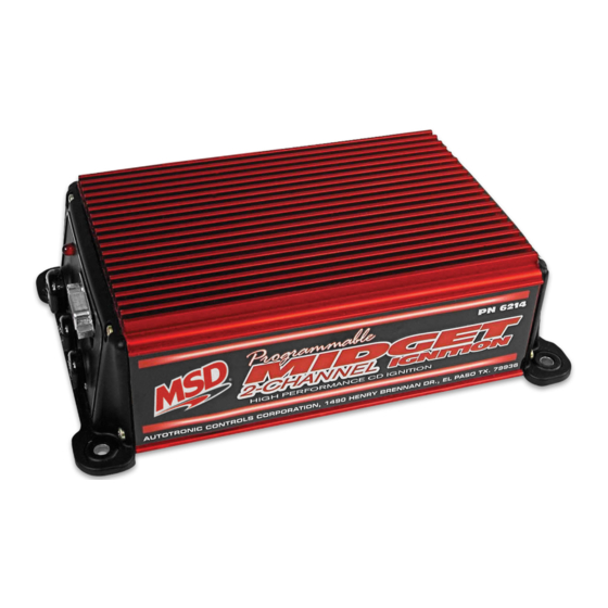
MSD Ignition DIS-2 Installation Instructions Manual

MSD Ignition DIS-2 Installation Instructions Manual

Digital dual channel ignition, digital multi channel ignition

Advertisement

MSD Digital DIS-2 Dual Channel Ignition
MSD Digital DIS-4 Multi Channel Ignition
The MSD Digital DIS-2 Dual Channel Ignition can be used on 4-cylinder engines equipped with
two dual output coils. The MSD Digital DIS-4 Multi Channel Ignition can be used on 4, 6 or 8-cylinder
engines equipped with up to four dual output coils. The MSD Digital DIS Ignition will accept trigger
inputs from electronic DIS type ignition systems.
Parts Included
1 - MSD Digital DIS-2 or DIS-4 Ignition
12 - Connectors, Butt Splice
2 - Program Switch Covers
1 - Cable Assembly
1 - Bypass Plug
NOTE: It is recommended that you have the Service Manual and wiring diagram for your vehicle
before beginning the installation of the MSD Digital DIS Ignition.
WARNING: Before installing the MSD Digital DIS Ignition, disconnect the battery cables. When
disconnecting the battery cables, always remove the Negative (-) cable first and install
it last.
NOTE: 1. Solid Core spark plug wires cannot be used with an MSD DIS Ignition.
2. Vehicles originally equipped with a CD ignition cannot use an MSD DIS Ignition.
TECHNICAL FEATURES - DIGITAL DIS-2
Operating Voltage:
Operating Current:
RPM Capability:
Ignition Inputs:
Ignition Outputs:
LED Indicator:
Tach Output:
Rev Limiter:
Spark Duration:
Energy Output Max:
Output Voltage:
Weight & Size:
Potting:
AUTOTRONIC CONTROLS CORPORATION
Read these instructions before attempting this installation!
10-18 volts (neg. ground)
4.0 Amperes @ 10,000 RPM
14,000 RPM - 4-Cyl. @ 14 volts
2 - DIS Type
2 - DIS Type
Ign. trigger, low battery voltage
(+) 12 volt square wave,
40° duration
High RPM - Adjustable
Low RPM - Adjustable
20°- 4-Cyl. Max Sparks - 12
105-115 milliJoules per spark.
1540 milliJoules per sequence.
Primary (Into Coil): 460-480 volts
Secondary: (w/stock coil)
40,000 volts
3.7 lbs., 8.5"L x 4.5"W x 2.2"H
Ciba Polyurethane
PN 6211
PN 6215
Parts not included but may be needed
Tach/Fuel Adapter(s)
PN 8912
IMPORTANT
TECHNICAL FEATURES - DIGITAL DIS-4
Operating Voltage:
Operating Current:
RPM Capability:
Ignition Inputs:
Ignition Outputs:
LED Indicator:
Tach Output:
Rev Limiter:
Spark Duration:
Energy Output Max:
Output Voltage:
Weight & Size:
Potting:
• 1490 HENRY BRENNAN DR., EL PASO, TEXAS 79936 • (915) 857-5200 • FAX (915) 857-3344
10-18 volts (neg. ground)
7.4 Amperes @ 10,000 RPM
14,000 RPM - 4, 6, 8-Cyl. @ 14 volts
2, 3, 4 - DIS Type
2, 3, 4 - DIS Type
Ign. trigger, low battery voltage
(+) 12 volt square wave,
40° Duration
High RPM - Adjustable
Low RPM - Adjustable
20°- 4, 6, 8-Cyl. Max Sparks - 12
105-115 milliJoules per spark.
1540 milliJoules per sequence.
Primary (Into Coil): 460-480 volts
Secondary: (w/stock coil)
40,000 volts
4.5 lbs., 9.5"L x 4.5"W x 2.2"H
Ciba Polyurethane

Advertisement

Table of Contents
loading
Need help?

Need help?

Do you have a question about the DIS-2 and is the answer not in the manual?

Questions and answers

Subscribe to Our Youtube Channel

Summary of Contents for MSD Ignition DIS-2

  • Page 1 MSD Digital DIS-4 Multi Channel Ignition PN 6215 The MSD Digital DIS-2 Dual Channel Ignition can be used on 4-cylinder engines equipped with two dual output coils. The MSD Digital DIS-4 Multi Channel Ignition can be used on 4, 6 or 8-cylinder engines equipped with up to four dual output coils.
  • Page 2: Theory Of Operation

    The MSD Ignition features a capacitor which is quickly charged to 460-480 volts and stores it until the ignition is triggered. With the CD design, the voltage sent to the coil is always at full power even at high rpm.
  • Page 3 Every application is different and should be tested and tuned. MOUNTING The MSD Ignition may be mounted in any location except on the engine or near the exhaust manifold. Excessive heat at these locations may cause damage to the ignition. It can be mounted in any position.
  • Page 4: General Wiring Information

    GENERAL WIRING INFORMATION Wire Length: All of the wires of the MSD Ignition may be shortened as long as quality connectors are used or soldered in place. To lengthen the wires, use one size bigger gauge wire (12 gauge for the power leads and 16 gauge for all other wires) with proper connections.
  • Page 5 INSTALLATION INSTRUCTIONS WIRING TO THE FACTORY IGNITION SYSTEM NOTE: The factory rev limiter and all timing functions will still function as normal with the MSD Digital DIS Ignition installed. 1. Locate the ignition coils and identify which wire leading to the coil(s) has 12 volts on it with the ignition key in the On position.
  • Page 6 INSTALLATION INSTRUCTIONS Wiring before installation of the MSD. Figure 4 AUTOTRONIC CONTROLS CORPORATION • 1490 HENRY BRENNAN DR., EL PASO, TEXAS 79936 • (915) 857-5200 • FAX (915) 857-3344...
  • Page 7 INSTALLATION INSTRUCTIONS Wiring after installation of the MSD. Figure 5 AUTOTRONIC CONTROLS CORPORATION • 1490 HENRY BRENNAN DR., EL PASO, TEXAS 79936 • (915) 857-5200 • FAX (915) 857-3344...
  • Page 8: Theft Deterrent

    INSTALLATION INSTRUCTIONS STAGING REV LIMIT (TWO STEP) The Two Step feature provides the capability of switching between two rpm limits - High and Low. The limits are set using the Staging Rev Limit and the Max Speed Rev Limit. To activate the Staging Rev Limit function, connect the Light Blue wire to a momentary switched ground (Figure 6).
  • Page 9: Programmable Features

    INSTALLATION INSTRUCTIONS PROGRAMMABLE FEATURES Below is a list of the DIS 2 and 4’s programmable features. As illustrated in figure 8, the factory ECU max timing and rev limit setting cannot be overridden. SWITCH 1 Max/Min Rev Limit - Selector S1 raises the Staging Rev Limit and Max Speed Rev Limit by 4000.
  • Page 10 INSTALLATION INSTRUCTIONS MAX/MIN REV LIMIT (+) STAGING REV LIMIT RETARD BEGIN SPEED Selector, S1, extends the Selectors S1, S2, S3 and S4 set the The Retard Begin Speed, S1, S2 and S3 range of the Max Speed Rev rpm point at which the Staging Rev Limit of Switch 3 determines the rpm point at Limit and the Staging Rev feature limits the engine rpm at.
  • Page 11: Wiring Diagrams

    The following wiring diagrams illustrate numerous installations on different vehicles and applications. If you experience difficulties when installing your MSD DIS-2 or DIS-4 Ignition, contact our Customer Service Department at (915) 855-7123 Monday - Friday, 8am - 5pm mountain time or e-mail us at: msdtech@msdignition.com.
  • Page 12 INSTALLATION INSTRUCTIONS Figure 12 GENERAL DIS WIRING Typical 6-cylinder application (factory wiring) Figure 13 GENERAL DIS WIRING Typical 6-cylinder application with DIS-4 Ignition AUTOTRONIC CONTROLS CORPORATION • 1490 HENRY BRENNAN DR., EL PASO, TEXAS 79936 • (915) 857-5200 • FAX (915) 857-3344...
  • Page 13 INSTALLATION INSTRUCTIONS Figure 14 GENERAL DIS WIRING Typical 8-cylinder application (factory wiring) Figure 15 GENERAL DIS WIRING Typical 8-cylinder application with DIS-4 Ignition AUTOTRONIC CONTROLS CORPORATION • 1490 HENRY BRENNAN DR., EL PASO, TEXAS 79936 • (915) 857-5200 • FAX (915) 857-3344...
  • Page 14: Pre-Start Checklist

    INSTALLATION INSTRUCTIONS PRESTART CHECK LIST • The only wires connected to the coil negative (-) terminals/wires are the MSD Brown/White, Brown/ Green, Brown/Yellow, Brown/Violet. • The only wire connected to the coil positive (+) terminals/wires is the MSD Brown/Orange. • The only wires connected to the factory harness wires (trigger input) are the MSD White, Green, Yellow, Violet.
  • Page 15: Troubleshooting

    INSTALLATION INSTRUCTIONS Figure 16 MSD DIS-2 IGNITION WITH PN 8912 ADAPTER TROUBLESHOOTING Every MSD Digital DIS Ignition undergoes numerous quality control checks including a four hour burn-in test. If you experience a problem with your MSD, our research has shown that the majority of problems are due to improper installation or poor connections.
  • Page 16: Checking For Spark

    On position. If 12 volts is not present, find another switched 12 volt source and repeat the test. NOTE: Some vehicles will require cranking the engine to provide +12V to the MSD Ignition Red wire.

This manual is also suitable for:

Dis-462116215

Table of Contents