Advertisement
Quick Links
Specifi cations
Power Supply
Model
Power Voltage
Usage
Option
24U
24VAC/DC +/-10% (50-
180mA
60Hz AC power)
120
120 VAC +/-10% 50-60Hz
50mA
240
240VAC +/-10% 50-60Hz
25mA
Current Input
5 Amp secondary CT or
ProteCT (0.333VAC)
5A series: 50-3000A)
MV series: 5-1500A)
Voltage Input
347/600VAC 3-PhaseWye system
with earthed neutral, Measurement
Category III
600VAC 3-Phase Delta system,
Measurement Category III
Output
Modbus RTU (RS485)
KWH pulse contact,
40mA and 50 VDC max.
Accuracy
< 1%
Linearity
< 0.5%
Isolation Voltage
2500 VAC
Frequency Range
Auto. selects 50 or 60 hertz
Operating Temp.
14 - 122° F (-10º to +50° C)
Enclosure
UL94 V0 Rated
Environmental
0–95% Relative Humidity non-
condensing
Altitude to 2000 meters
Pollution Degree 2
Indoor Use
EMC/Immunity
EN50081-1, EN50082-2
Agency Approvals
UL/cUL Listed
Model Number Key
APN - 600 - MV - 120 - MOD
OVP Category
II
II
II
CURRENT INPUT:
5A - 5 amp secondary CT
MV - 0.333 VAC secondary (ProteCT)
VOLTAGE INPUT RANGE:
600 - Line voltage 100 - 600 VAC
POWER MONITOR TYPE:
APN - AC Power Monitor, Digital Output
Know Your Power
Other NK Technologies Products Include:
AC & DC Current Transducers
AC & DC Current Operated Switches
1φ & 3φ Power Transducers
Current & Potential Transformers (CTs & PTs)
3511 Charter Park Drive, San Jose, CA 95136
800-959-4014 or 408-871-7510 Phone
408-871-7515 FAX
sales@nktechnologies.com, www.nktechnologies.com
OUTPUT TYPE:
MOD - Modbus RTU (RS485)
POWER SUPPLY:
24U - 24VAC/DC
120 - 120VAC
240 - 240 VAC
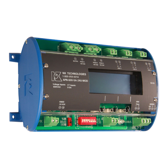
INSTRUCTIONS
APN SERIES
AC Power Monitor
Maximum 600 Volts
Modbus RTU Output
Quick "How To" Guide
1. Ensure correct model was chosen for Current Input
Type: 5 amp or low-voltage 333mVAC.
2. Mount the monitor to a DIN rail using integrated
mounting clips on backside of power monitor.
3. Connect non-energized 3 phase input voltage (term.
2-4, neutral 1 if used) . 1 amp fuses are recommend-
ed. Tighten all terminals to 5-7 inch-pounds.
4. Connect Current Transformer Inputs (term. 5-10).
The white wire (or X1 terminal) from a CT is posi-
tive or phase indicator (6-8-10).
5. Select baud rate, network address
6. Connect network output (term. 11-13)
7. Connect power supply (term. 16-17)
8. Connect kWH pulse output if needed
9. Energize the monitor and primary circuit.
10. Set CT ratio and KWH type using buttons below
the display.
APN Instruction Sheet Rev 6 03/17 P/N791000004
Advertisement

Related Manuals for NK TECHNOLOGIES APN Series

Summary of Contents for NK TECHNOLOGIES APN Series
- Page 1 The white wire (or X1 terminal) from a CT is posi- Altitude to 2000 meters tive or phase indicator (6-8-10). Pollution Degree 2 Other NK Technologies Products Include: AC & DC Current Transducers Indoor Use 5. Select baud rate, network address AC &...
- Page 2 Description Set Up Screens Modbus Address and Baud Rate APN Series Power Monitors are designed to monitor AC loads and The node address is When the fi eld input connections have been made (current provide data points displaying line voltage, current, instantaneous...
- Page 3 The APN can be used with many current trans- About MODBUS and the APN Power Monitor After completing the set up programming, the MODBUS® Protocol is a messaging structure, widely formers, and it must be programmed for the LCD display can be changed to show several data used to establish master-slave communication between range you will be using.
- Page 4 Table 1 Register Map - Read Only About MODBUS and the Monitor (continued) the fi rst fi eld (the address fi eld) is 8 data bits, with the least signifi cant bit sent fi rst Address Register Type Description 1 bit for even parity received, the Monitor decodes 40001 Integer, 16 bit...