Table of Contents
Advertisement
Quick Links
Advertisement
Table of Contents

Summary of Contents for MotoCrane COMMAND CONSOLE PRO
- Page 1 COMMAND Console Operation Manual v1.0 NOVEMBER 2021...
-
Page 2: Safety Signal Words
To minimize risk of serious injury, death or damage, before using the MotoCrane COMMAND Console, all drivers and operators must read this Operation Manual and all on-product labels. All practices and procedures stated herein are required for the proper and safe operation of the COMMAND Console. -
Page 3: Table Of Contents
IMPORTANT PRODUCT & SAFETY INSTRUCTIONS Safety IMPORTANT: Restricted Use Statement Disclaimer and Limitations of Liability Limited Warranty Intellectual Property System Overview COMMAND Console PRO COMMAND Console LITE COMMAND Console Setup Setup “at a glance” MotoCrane COMMAND Console COMMAND Console Touchscreen Interface Interface Layout... -
Page 4: Before The First Drive
Do the following before using the COMMAND Console for the first time. 1. Read this Operation Manual 2. Read the Warranty in the Terms of Sale 3. Watch the Video Tutorials at www.motocrane.com/knowledge-base 4. Recommended: Attend MotoCrane Training for in-person demonstration... -
Page 5: Important Product & Safety Instructions
IMPORTANT PRODUCT & SAFETY INSTRUCTIONS Safety The MotoCrane COMMAND Console is not a toy and can cause serious injury, death or damage if not used properly. You must exercise caution during use of the COMMAND Console to ensure a safe filming environment for everyone. This Operation Manual describes safe operation and should be read in conjunction with the online training videos or additional in-person training. -
Page 6: Limited Warranty
Terms and Conditions of Sale for your COMMAND Console for a complete description of this limited warranty. This Limited Warranty is incorporated by reference into this Operation Manual. Intellectual Property MotoCrane™, and are trademarks of MotoCrane, LLC. You may not use the trademarks of MotoCrane, LLC without express written permission. All rights reserved. -
Page 7: System Overview
System Overview COMMAND Console PRO... -
Page 8: Command Console Lite
COMMAND Console LITE... -
Page 9: Command Console Setup
Setup “at a glance” In order to be operational, the COMMAND Console must be connected to the PSU. 1. Setup your MotoCrane remote arm system as described in its corresponding Operation Manual. 2. Once ready, connect the COMMAND Console to the PSU using the Controller COM Cable. -
Page 10: Motocrane Command Console
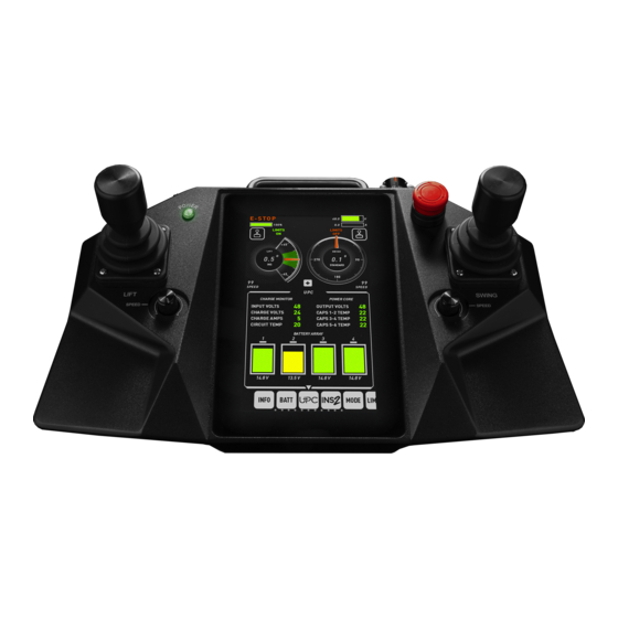
MotoCrane COMMAND Console The MotoCrane COMMAND Console PRO houses two single-axis joysticks for Swing and Lift axis control, whereas the LITE version houses one dual-axis joystick. Both are equipped with speed adjustment knobs for easy user adjustment, and a touch screen color display for configuration, monitoring, and advanced settings. -
Page 11: Command Console Touchscreen Interface
COMMAND Console Touchscreen Interface Interface Layout The COMMAND Console features a touchscreen interface for monitoring real-time system data, configuring settings like range of motion limits, and also performing tuning or calibrations required for your application. The layout is organized into 4 sections (Header, Dashboard, Control Panel, and Dock) to allow critical system information like battery voltage and arm position to always be displayed, even when adjusting settings or monitoring system performance. -
Page 12: Header
Header The Header contains basic critical system information like System Input Voltage, Total System Current Draw (in Amps) and an indicator for when the system is Disarmed (E-Stop pressed down). If the UPC (Ultracapacitor Power Core) is connected, you’re also able to monitor how much energy is stored within the UPC (charge level). -
Page 13: Dashboard
Dashboard The dashboard contains axis position and control information like Lift and Swing axis position gauges and their corresponding joystick settings. The Dashboard indicates whether range of motion Limits are ON or OFF and displays a green region for the configured Limits region when Limits are turned ON. -
Page 14: Joystick Settings
Joystick Settings Joystick settings for either axis can be accessed and adjusted by touching the Joystick Icon located on the dashboard. Smoothing and Deadband are adjusted by touching and dragging the vertical sliders up and down to the desired levels. Axis inversion can be toggled ON or OFF by tapping the INVERT toggle switch. -
Page 15: Expanded Dashboard
Expanded Dashboard The Dashboard can be Expanded to offer a more focused view of Lift and Swing position by pressing the “+” icon on the Dashboard. This can be helpful after all settings/configurations have been completed and only arm position is of primary interest. The Header is retained within the Expanded Dashboard for monitoring system power and E-STOP/DISARM Status. -
Page 16: Control Panel
Control Panel The Control Panel is a dedicated region for settings, configuration/calibrations, and diagnostics. Below is an example of the “Limits” Control Panel:... -
Page 17: Dock
Dock The Dock is used for navigating the various Control Panels that are available. To navigate, simply touch the icon of the desired Control Panel, or swipe right/left to see more options. -
Page 18: Information
Information Displays system firmware and usage information. This information is sometimes used by MotoCrane Technical Support for diagnosing or prescribing service procedures and/or maintenance. -
Page 19: Battery Bank (Hyper-Only)
Battery Bank (HYPER-ONLY) MotoCrane HYPER has dual on-board 48v battery banks, which are charged via the MotoCrane Powerlink when connected to a 120VAC source. The Battery Bank Control Panel is used for monitoring status of both banks. -
Page 20: Upc (Radical-Only)
UPC (RADICAL-ONLY) The MotoCrane Ultracapacitor Power Core (UPC) is a power accessory that provides 48V power from common V-Mount/Gold Mount Batteries and/or the vehicles own 12V battery when using the MotoCrane 12VA. This Control Panel is used for monitoring UPC-specific diagnostics such as input/output voltage, V-Mount Battery levels, and thermal status of the power core. -
Page 21: Ins 2 Advanced Stabilization
INS 2 Advanced Stabilization Displays data from the MotoCrane INS Advanced Stabilization sensor (if connected) and allows configuration of INS 2 tuning parameters. Refer to the INS 2 Advanced Stabilization Operation manual. The latest version can be found at www.motocrane.com/knowledge-base. -
Page 22: Limits
Limits Both Swing and Lift axes of MotoCrane RADICAL and HYPER are equipped with high-accuracy encoders that allow the range of motion to be limited within a configured region. Limits cannot be used when the axis is in the “SETUP” Control Mode, which is an open-loop/non-encoded control mode. -
Page 23: Control Mode
Control Mode Both Axes of RADICAL and HYPER can operate in various “Control Modes” which use different types of input for arm positioning. SETUP Mode- This mode is used for during physical setup or bench-testing, when no payloads are attached. Because this is an open-loop Control Mode, Limits are not available in this Control Mode. -
Page 24: Setup
Setup Used for less-frequently adjusted configurations. Balance Test- Helps to detect any Lift Axis imbalance between payload and counterweight by eliminating the electromotive torque present in a gear-reduced powertrain. Joystick Calibration- Calibrates minimum, maximum, and neutral positions for the Joystick along both the Lift and Swing axes. -
Page 25: Diagnostics
Diagnostics Motor Command- Joystick value commanding movement to the motor driver circuit. It’ s maximum and minimum value is based on the SPEED value, and will increase/decrease based on SMOOTH value. Motor RPM- Speed of the brushless motor in Revolutions Per Minute. Motor Current- The current consumption of the brushless motor in Amperes Motor Temperature- The temperature of the brushless motor housing in degrees Celsius Driver Temperature- The temperature the motor driver circuit in degrees Celsius... -
Page 26: Status
Status Shows system errors/warnings that are currently active in the system. To view any active Errors/Warnings, press the “!” button on the COMMAND Console when it is illuminated. The description indicates what the error/warning consists of, while the code number indicates the specific error/warning event. -
Page 27: System Log
System Log The SYSTEM LOG page shows recent system errors reported to the COMMAND Console. When an error or warning condition clears, the STATUS page will not display the error anymore, but the SYSTEM LOG page will, along with the time elapsed since the error was triggered. -
Page 28: Code Lookup
Displays all system warnings and errors that can be triggered along with a summarized service procedure. Refer to this page to lookup an error code displayed in the STATUS/SYSTEM LOG control panels. For more information on error codes and troubleshooting your remote arm system, refer to the corresponding Troubleshooting Guide found at www.motocrane.com/knowledge-base. -
Page 29: Known Hazards
For UPC errors, refer to the UPC Operation Manual. For INS errors, refer to the INS 2 Advanced Stabilization Operation Manual. The latest versions of these operation manuals can be found at www.motocrane.com/knowledge-base Maintenance None required - contact Technical Support if you believe the unit requires service or maintenance. -
Page 30: Mounting/Dimensions Of Command Console
Mounting/Dimensions of COMMAND Console The COMMAND Console PRO is equipped with 3x ¼-20 and 2x ⅜-16 threaded mounting points on the top of the controller, and also features a passive V-Mount Battery sled on the back. The V-Mount Battery sled is not for providing power to COMMAND Console, and is only used as a mounting plate for the battery so that it can provide power for other accessories mounted to the COMMAND Console. -
Page 31: Revision History
Initial Release MotoCrane Support support@motocrane.com This content is subject to change. Download the latest version from www.motocrane.com/knowledge-base If you have any questions about this document, please contact MotoCrane, LLC by sending a message to contact@motocrane.com. ©2021 MotoCrane, LLC. All rights reserved.
Need help?
Do you have a question about the COMMAND CONSOLE PRO and is the answer not in the manual?
Questions and answers